|
ac5uuw00007801
REAR BODY CONTROL MODULE (RBCM) REMOVAL/INSTALLATION
id094000002000
WITHOUT SCR SYSTEM
1. When replacing the rear body control module (RBCM), perform the configuration. (See REAR BODY CONTROL MODULE (RBCM) CONFIGURATION (USING READ/WRITE FUNCTION).)
2. Operate the door lock actuator using the following procedure and deplete the energy stored in the backup power supply.
3. Disconnect the negative battery terminal. (See NEGATIVE BATTERY TERMINAL DISCONNECTION/CONNECTION.)
4. Remove the following parts:
5. Pull back the trunk side trim (LH) to a position which allows for the removal of the rear body control module (RBCM). (See TRUNK SIDE TRIM REMOVAL/INSTALLATION.)
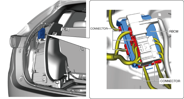
6. Disconnect the connectors shown in the figure.
ac5uuw00007801
|
7. While pressing the rear body control module (RBCM) tab in the direction of arrow (1) shown in the figure, pull it in the direction of arrow (2) to detach the tab from the body.
ac5uuw00005934
|
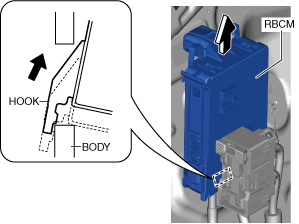
8. Pull the rear body control module (RBCM) up in the direction of the arrow to detach the hook from the body.
ac5uuw00005935
|
9. Remove the rear body control module (RBCM).
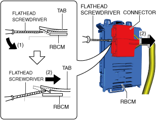
10. Insert a tape-wrapped flathead screwdriver into the position shown in the figure.
ac5uuw00005936
|
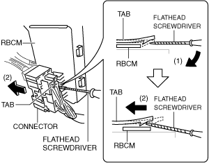
11. Move the screwdriver in the direction of arrow (1) shown in the figure and pull the connector in the direction of arrow (2) to detach its tab from the rear body control module (RBCM).
12. Pull the connector in the direction of arrow (2) shown in the figure and remove it.
13. Install in the reverse order of removal.
WITH SCR SYSTEM
1. When replacing the rear body control module (RBCM), perform the configuration. (See REAR BODY CONTROL MODULE (RBCM) CONFIGURATION (USING READ/WRITE FUNCTION).)
2. Operate the door lock actuator using the following procedure and deplete the energy stored in the backup power supply.
3. Disconnect the negative battery terminal. (See NEGATIVE BATTERY TERMINAL DISCONNECTION/CONNECTION.)
4. Remove the following parts:
5. Pull back the trunk side trim (LH) to a position which allows for the removal of the rear body control module (RBCM). (See TRUNK SIDE TRIM REMOVAL/INSTALLATION.)
6. Disconnect the connectors shown in the figure.
ac5wzw00011936
|
7. While pressing the rear body control module (RBCM) tab in the direction of arrow (1) shown in the figure, pull it in the direction of arrow (2) to detach the tab from the body.
ac5wzw00011937
|
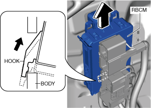
8. Pull the rear body control module (RBCM) up in the direction of the arrow to detach the hook from the body.
ac5wzw00011938
|
9. Remove the rear body control module (RBCM).
10. Insert a tape-wrapped flathead screwdriver into the position shown in the figure.
ac5wzw00011939
|
11. Move the screwdriver in the direction of arrow (1) shown in the figure and pull the connector in the direction of arrow (2) to detach its tab from the rear body control module (RBCM).
12. Pull the connector in the direction of arrow (2) shown in the figure and remove it.
13. Insert a tape-wrapped flathead screwdriver into the position shown in the figure.
ac5wzw00011940
|
14. Move the screwdriver in the direction of arrow (1) shown in the figure and pull the connector in the direction of arrow (2) to detach its tab from the rear body control module (RBCM).
15. Pull the connector in the direction of arrow (2) shown in the figure and remove it.
16. Install in the reverse order of removal.