 |
ac5wzw00002287
POWER BRAKE UNIT REMOVAL/INSTALLATION [R.H.D.]
id041100801852
1. Remove the windshield wiper arm and blade. (See WINDSHIELD WIPER ARM AND BLADE REMOVAL/INSTALLATION.)
2. Remove the cowl grille. (See COWL GRILLE REMOVAL/INSTALLATION.)
3. Remove the windshield wiper motor and link. (See WINDSHIELD WIPER MOTOR AND LINK REMOVAL/INSTALLATION.)
4. Remove the cowl panel. (See COWL PANEL REMOVAL/INSTALLATION.)
5. Remove the insulator. (See EXHAUST SYSTEM REMOVAL/INSTALLATION [SKYACTIV-G 2.0, SKYACTIV-G 2.5].) (See EXHAUST SYSTEM REMOVAL/INSTALLATION [SKYACTIV-D 2.2].)
6. Remove the master cylinder. (See MASTER CYLINDER REMOVAL/INSTALLATION.)
7. Remove the power brake unit vacuum sensor. (See POWER BRAKE UNIT VACUUM SENSOR REMOVAL/INSTALLATION.)
8. Remove the washer funnel. (See WASHER TANK REMOVAL/INSTALLATION.)
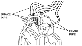
9. Disconnect the brake pipes from the DSC HU/CM.
ac5wzw00002287
|
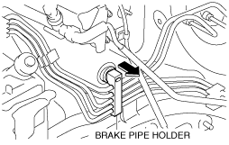
10. Detach the brake pipe holder from the vehicle.
ac5wzw00002530
|
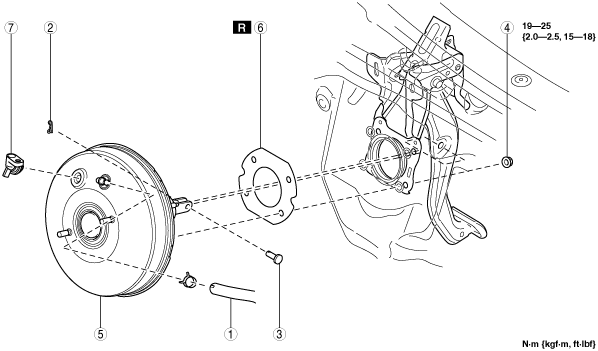
11. Remove in the order indicated in the table.
12. Install in the reverse order of removal.
13. After installation, add brake fluid, bleed the air, and inspect for fluid leakage. (See BRAKE FLUID AIR BLEEDING.)
14. Remove the brake switch. (See BRAKE PEDAL REMOVAL/INSTALLATION [R.H.D.].)
15. Inspect the brake pedal. (See BRAKE PEDAL INSPECTION.)
16. Install a new brake switch. (See BRAKE PEDAL REMOVAL/INSTALLATION [R.H.D.].)
ac5wzw00000217
|
|
1
|
Vacuum hose
|
|
2
|
Snap pin
|
|
3
|
Clevis pin
|
|
4
|
Nut
|
|
5
|
Power brake unit
|
|
6
|
Gasket
|
|
7
|
Power brake unit vacuum sensor joint
|