 |
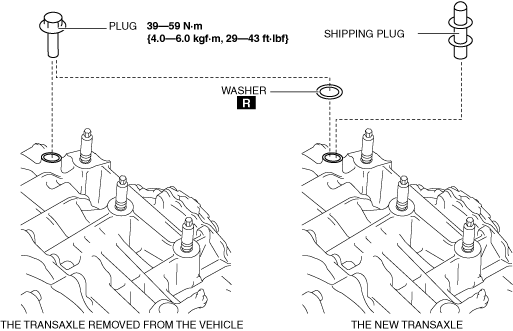
ac5wzw00004341
AUTOMATIC TRANSAXLE REMOVAL/INSTALLATION [GW6AX-EL]
id0517i21172i4
Replacement Part
|
washer
Quantity: 1
Location of use: plug
|
Removal
1. Disconnect the negative battery cable. (See NEGATIVE BATTERY CABLE DISCONNECTION/CONNECTION [SKYACTIV-D 2.2].)
2. Remove the air cleaner and air hose as a single unit. (See INTAKE-AIR SYSTEM REMOVAL/INSTALLATION [SKYACTIV-D 2.2].)
3. Remove the battery tray. (See BATTERY REMOVAL/INSTALLATION [SKYACTIV-D 2.2].)
4. Disconnect the wiring harness clip from the transaxle.
ac5wzw00004341
|
5. Remove the splash shield. (See SPLASH SHIELD REMOVAL/INSTALLATION.)
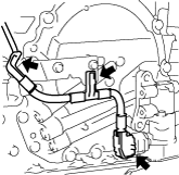
6. Disconnect the electric AT oil pump connector and electric AT oil pump harness from the transaxle.
ac5wzw00004342
|
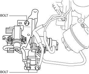
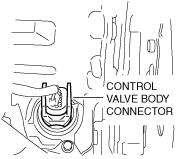
7. Disconnect the control valve body connector.
ac5wzw00004343
|
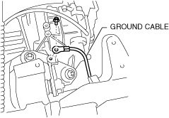
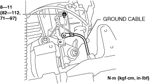
8. Disconnect the ground cable.
ac5wzw00004344
|
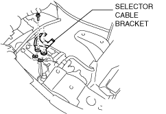
9. Disconnect the selector cable from the transaxle. (See AUTOMATIC TRANSAXLE SHIFT MECHANISM REMOVAL/INSTALLATION.)
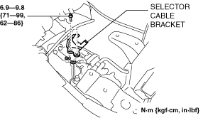
10. Remove the selector cable bracket.
ac5wzw00004346
|
11. Remove the EGR cooler. (See EGR COOLER REMOVAL/INSTALLATION [SKYACTIV-D 2.2].)
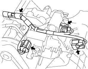
12. Disconnect the solenoid valve connectors and the wiring harness from the solenoid valve component. (See COMPRESSOR BYPASS SOLENOID VALVE REMOVAL/INSTALLATION [SKYACTIV-D 2.2].) (See REGULATING SOLENOID VALVE REMOVAL/INSTALLATION [SKYACTIV-D 2.2].) (See WASTEGATE SOLENOID VALVE REMOVAL/INSTALLATION [SKYACTIV-D 2.2].)
ac5wzw00004347
|
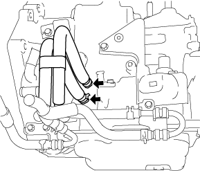
13. Disconnect the solenoid valve component from the ATX with the hose still connected, and set it out of the way. (See COMPRESSOR BYPASS SOLENOID VALVE REMOVAL/INSTALLATION [SKYACTIV-D 2.2].) (See REGULATING SOLENOID VALVE REMOVAL/INSTALLATION [SKYACTIV-D 2.2].) (See WASTEGATE SOLENOID VALVE REMOVAL/INSTALLATION [SKYACTIV-D 2.2].)
ac5wzw00004348
|
14. Disconnect the breather hose from the transaxle.
15. Remove the joint cover. (See STEERING WHEEL AND COLUMN REMOVAL/INSTALLATION.)
16. Disconnect the intermediate shaft from the steering gear and linkage. (See STEERING WHEEL AND COLUMN REMOVAL/INSTALLATION.)
17. Remove the front tires. (See GENERAL PROCEDURES (SUSPENSION).)
18. Remove the front under cover No.2. (See FRONT UNDER COVER No.2 REMOVAL/INSTALLATION.)
19. Remove the front under cover No.1. (See FRONT UNDER COVER No.1 REMOVAL/INSTALLATION.)
20. Drain the ATF. (See AUTOMATIC TRANSAXLE FLUID (ATF) REPLACEMENT [GW6A-EL, GW6AX-EL].)
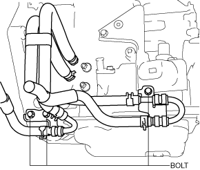
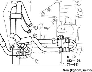
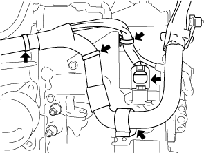
21. Disconnect the oil hose from the transaxle. (With oil cooler No.2) (See OIL COOLER REMOVAL/INSTALLATION [GW6A-EL, GW6AX-EL].)
ac5wzw00004349
|
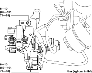
22. Set the oil pipe component in a place which does not interfere with the servicing. (With oil cooler No.2) (See OIL COOLER REMOVAL/INSTALLATION [GW6A-EL, GW6AX-EL].)
ac5wzw00004350
|
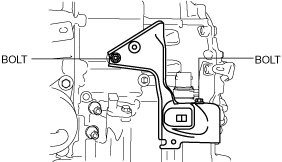
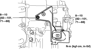
23. Remove the bracket from the transaxle.
ac5wzw00004351
|
24. Disconnect the oil cooler from the transaxle with the hose connected. (Except Automatic Transaxle Replacement) (See OIL COOLER REMOVAL/INSTALLATION [GW6A-EL, GW6AX-EL].)
25. Disconnect the water hose from the oil cooler. (Automatic Transaxle Replacement) (See OIL COOLER REMOVAL/INSTALLATION [GW6A-EL, GW6AX-EL].)
26. Remove the starter. (See STARTER REMOVAL/INSTALLATION [SKYACTIV-D 2.2].)
27. Remove the blind cover.
ac5wzw00004352
|
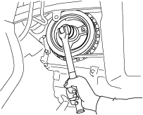
28. Hold the crankshaft pulley to prevent drive plate from rotating.
ac5wzw00004353
|
29. Remove the torque converter nuts from the starter installation hole.
ac5wzw00004354
|
30. Disconnect the front ABS wheel-speed sensors from the steering knuckles. (See FRONT ABS WHEEL-SPEED SENSOR REMOVAL/INSTALLATION.)
31. Disconnect the clips securing the brake hose from the front shock absorbers. (See FRONT BRAKE (DISC) REMOVAL/INSTALLATION.)
32. Disconnect the tie-rod end ball joints from the steering knuckles. (See STEERING GEAR AND LINKAGE REMOVAL/INSTALLATION.)
33. Disconnect the front lower arms from the steering knuckles. (See FRONT LOWER ARM REMOVAL/INSTALLATION.)
34. Disconnect the front stabilizer control links from the front stabilizer. (See FRONT STABILIZER REMOVAL/INSTALLATION.)
35. Disconnect the front drive shaft (LH) from the transaxle. (See FRONT DRIVE SHAFT REMOVAL/INSTALLATION.)
36. Remove the front drive shaft (RH) from the transfer. (See FRONT DRIVE SHAFT REMOVAL/INSTALLATION.)
37. Remove the propeller shaft. (See PROPELLER SHAFT REMOVAL/INSTALLATION.)
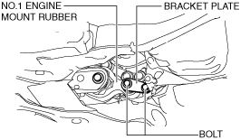
38. Remove the bracket plate. (See ENGINE DISASSEMBLY/ASSEMBLY [SKYACTIV-D 2.2].)
ac5wzw00004355
|
39. Remove the front crossmember component and No.1 engine mount rubber as a single unit. (See FRONT CROSSMEMBER REMOVAL/INSTALLATION.)
40. Remove the transfer. (See TRANSFER REMOVAL/INSTALLATION [GW6AX-EL].)
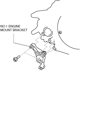
41. Remove the No.1 engine mounting bracket.
ac5wzw00004356
|
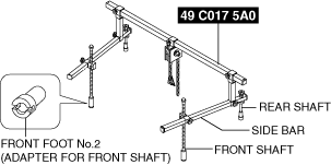
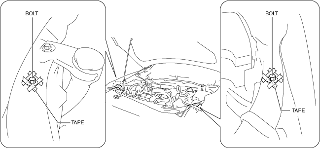
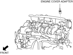
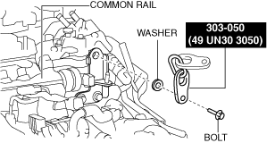
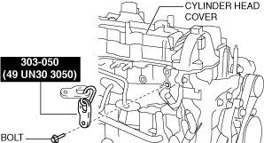
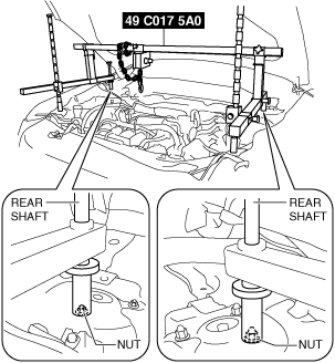
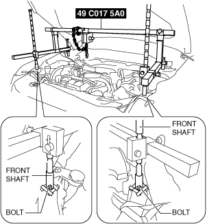
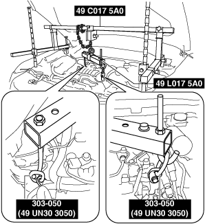
42. Install the SST using the following procedures.
ac5wzw00004357
|
ac5wzw00004358
|
ac5wzw00004359
|
Engine front side
ac5wzw00004361
|
Engine rear side
ac5wzw00004360
|
ac5wzw00004362
|
ac5wzw00004363
|
ac5wzw00004364
|
ac5wzw00004365
|
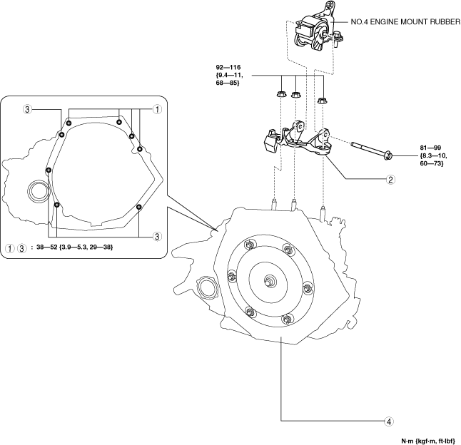
43. Remove in the order shown in the figure.
ac5wzw00004366
|
|
1
|
Transaxle mounting bolts (upper side)
|
|
2
|
No.4 engine mount bracket
|
|
3
|
Transaxle mounting bolts (lower side)
|
|
4
|
Transaxle
|
No.4 engine mount bracket removal note
1. Place alignment marks on the locations shown in the figure so that they can be assembled to the same positions as before removal.
ac5wzw00004367
|
2. Remove the No.4 engine mount bracket.
Transaxle mounting bolt removal note
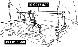
1. Adjust the SST and lean the engine toward the transaxle.
ac5wzw00004368
|
2. Support the transaxle on a jack.
ac5wzw00004369
|
3. Remove the transaxle mounting bolts (lower side).
4. Remove the transaxle.
Installation
1. If the transaxle is replaced with a new one, perform the following procedure.
ac9uuw00011693
|
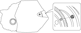
2. Verify that the torque converter stud bolts are inserted into the drive plate bolt holes from the starter installation hole.
ac5wzw00004370
|
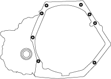
3. Install the transaxle mounting bolts.
ac5wzw00004371
|
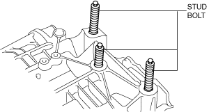
4. Tighten the stud bolts for the transaxle.
ac5wzw00004372
|
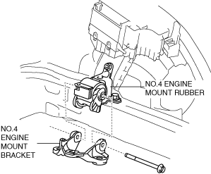
5. Install the No.4 engine mount bracket to No.4 engine mount rubber, and temporarily tighten the installation bolt.
ac5wzw00004373
|
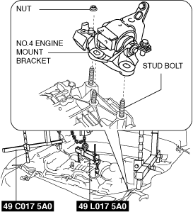
6. Pull up the transaxle using the SSTs, pass the transaxle stud bolts through the No.4 engine mount bracket, and temporarily tighten the No.4 engine mount installation nuts.
ac5wzw00004374
|
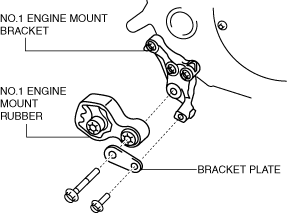
7. Install the No.1 engine mounting bracket.
ac5wzw00004375
|
8. Install the transfer. (See TRANSFER REMOVAL/INSTALLATION [GW6AX-EL].)
9. Install the front crossmember component and No.1 engine mount rubber as a single unit. (See FRONT CROSSMEMBER REMOVAL/INSTALLATION.)
10. Temporarily install the No.1 engine mount rubber and bracket plate.
ac5wzw00004376
|
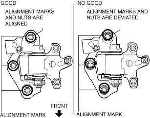
11. Align the alignment marks on the No.4 engine mount bracket and nuts, and temporarily tighten the nuts shown in the figure.
ac5wzw00004377
|
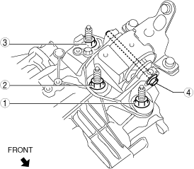
12. Tighten the No.4 engine mount bracket installation nuts and bolt in the order shown in the figure.
ac5wzw00004378
|
|
No. |
Tightening torque |
|---|---|
|
1, 2, 3
|
92—116 N·m {9.4—11 kgf·m, 69—85 ft·lbf}
|
|
4
|
81—99 N·m {8.3—10 kgf·m, 60—73 ft·lbf}
|
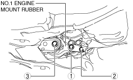
13. Tighten the No.1 engine mount rubber and bracket plate installation bolts.
ac5wzw00004379
|
|
No. |
Tightening torque |
|---|---|
|
1
|
140—163 N·m {15—16 kgf·m, 104—120 ft·lbf}
|
|
2
|
55—69 N·m {5.7—7.0 kgf·m, 41—50 ft·lbf}
|
|
3
|
130—164 N·m {14—16 kgf·m, 96—120 ft·lbf}
|
14. Install the propeller shaft. (See PROPELLER SHAFT REMOVAL/INSTALLATION.)
15. Remove the SST (49 C017 5A0).
16. Fix the crankshaft pulley to lock the torque converter against rotation.
ac5wzw00004380
|
17. Tighten the torque converter installation nut.
ac5wzw00004381
|
18. Install the blind cover.
ac5wzw00004382
|
19. Install the starter. (See STARTER REMOVAL/INSTALLATION [SKYACTIV-D 2.2].)
20. Install the front drive shaft (RH) to the transfer. (See FRONT DRIVE SHAFT REMOVAL/INSTALLATION.)
21. Install the front drive shaft (LH) to the transaxle. (See FRONT DRIVE SHAFT REMOVAL/INSTALLATION.)
22. Install the front stabilizer control links to the front stabilizer. (See FRONT STABILIZER REMOVAL/INSTALLATION.)
23. Install the front lower arms to the steering knuckles. (See FRONT LOWER ARM REMOVAL/INSTALLATION)
24. Install the tie-rod end ball joints to the steering knuckles. (See STEERING GEAR AND LINKAGE REMOVAL/INSTALLATION.)
25. Install the clips securing the brake hose to the front shock absorbers. (See FRONT BRAKE (DISC) REMOVAL/INSTALLATION.)
26. Install the front ABS wheel-speed sensors to the steering knuckles. (See FRONT ABS WHEEL-SPEED SENSOR REMOVAL/INSTALLATION.)
27. Connect the water hose to the oil cooler. (Automatic Transaxle Replacement) (See OIL COOLER REMOVAL/INSTALLATION [GW6A-EL, GW6AX-EL].)
28. Install the oil cooler to the transaxle with the hose connected. (Except Automatic Transaxle Replacement) (See OIL COOLER REMOVAL/INSTALLATION [GW6A-EL, GW6AX-EL].)
29. Install the bracket to the transaxle.
ac5wzw00004383
|
30. Install the oil pipe component. (With oil cooler No.2) (See OIL COOLER REMOVAL/INSTALLATION [GW6A-EL, GW6AX-EL].)
ac5wzw00004384
|
31. Connect the oil hose to the transaxle. (With oil cooler No.2) (See OIL COOLER REMOVAL/INSTALLATION [GW6A-EL, GW6AX-EL].)
ac5wzw00004385
|
32. Install the front under cover No.1. (See FRONT UNDER COVER No.1 REMOVAL/INSTALLATION.)
33. Install the front under cover No.2. (See FRONT UNDER COVER No.2 REMOVAL/INSTALLATION.)
34. Install the front tires. (See GENERAL PROCEDURES (SUSPENSION).)
35. Connect the intermediate shaft to the steering gear and linkage. (See STEERING WHEEL AND COLUMN REMOVAL/INSTALLATION.)
36. Install the joint cover. (See STEERING WHEEL AND COLUMN REMOVAL/INSTALLATION.)
37. Connect the breather hose to the transaxle.
38. Install the solenoid valve component. (See COMPRESSOR BYPASS SOLENOID VALVE REMOVAL/INSTALLATION [SKYACTIV-D 2.2].) (See REGULATING SOLENOID VALVE REMOVAL/INSTALLATION [SKYACTIV-D 2.2].) (See WASTEGATE SOLENOID VALVE REMOVAL/INSTALLATION [SKYACTIV-D 2.2].)
ac5wzw00004386
|
39. Connect the solenoid valve connectors and the wiring harness to the solenoid valve component. (See COMPRESSOR BYPASS SOLENOID VALVE REMOVAL/INSTALLATION [SKYACTIV-D 2.2].) (See REGULATING SOLENOID VALVE REMOVAL/INSTALLATION [SKYACTIV-D 2.2].) (See WASTEGATE SOLENOID VALVE REMOVAL/INSTALLATION [SKYACTIV-D 2.2].)
ac5wzw00004387
|
40. Install the EGR cooler. (See EGR COOLER REMOVAL/INSTALLATION [SKYACTIV-D 2.2].)
41. Install the selector cable bracket.
ac5wzw00004388
|
42. Connect the selector cable to the transaxle. (See AUTOMATIC TRANSAXLE SHIFT MECHANISM REMOVAL/INSTALLATION.)
43. Install the ground cable.
ac5wzw00004390
|
44. Connect the control valve body connector.
ac5wzw00004391
|
45. Connect the electric AT oil pump connector and electric AT oil pump harness from the transaxle.
ac5wzw00004392
|
46. Install the splash shield. (See SPLASH SHIELD REMOVAL/INSTALLATION.)
47. Connect the wiring harness to the transaxle.
ac5wzw00004393
|
48. Install the battery tray. (See BATTERY REMOVAL/INSTALLATION [SKYACTIV-D 2.2].)
49. Install the air cleaner and air hose as a single unit. (See INTAKE-AIR SYSTEM REMOVAL/INSTALLATION [SKYACTIV-D 2.2].)
50. Connect the negative battery cable. (See NEGATIVE BATTERY CABLE DISCONNECTION/CONNECTION [SKYACTIV-D 2.2].)
51. Add the ATF. (See AUTOMATIC TRANSAXLE FLUID (ATF) REPLACEMENT [GW6A-EL, GW6AX-EL].)
52. Perform the “TCM configuration” (automatic transaxle replacement). (SeeTCM CONFIGURATION [GW6A-EL, GW6AX-EL])
53. Perform the “Initial Learning” (automatic transaxle replacement). (See INITIAL LEARNING [GW6A-EL, GW6AX-EL].)
54. Perform the “Mechanical System Test”. (See MECHANICAL SYSTEM TEST [GW6A-EL, GW6AX-EL].)