ANTENNA FEEDER NO.3 INSPECTION
id092000813000
Without center display
1. Disconnect the negative battery cable. (See NEGATIVE BATTERY CABLE DISCONNECTION/CONNECTION [SKYACTIV-G 2.0, SKYACTIV-G 2.5].) (See NEGATIVE BATTERY CABLE DISCONNECTION/CONNECTION [SKYACTIV-G 2.0, SKYACTIV-G 2.5 (WITHOUT i-stop)].) (See NEGATIVE BATTERY CABLE DISCONNECTION/CONNECTION [SKYACTIV-D 2.2].)
2. Remove the following parts:
- (1) Front scuff plate (See FRONT SCUFF PLATE REMOVAL/INSTALLATION.)
- (2) Rear scuff plate (See REAR SCUFF PLATE REMOVAL/INSTALLATION.)
- (3) B-pillar lower trim (See B-PILLAR LOWER TRIM REMOVAL/INSTALLATION.)
- (4) Front seat belt adjusting cover (See FRONT SEAT BELT REMOVAL/INSTALLATION.)
- (5) Front seat belt upper anchor installation bolt (See FRONT SEAT BELT REMOVAL/INSTALLATION.)
- (6) B-pillar upper trim (See B-PILLAR UPPER TRIM REMOVAL/INSTALLATION.)
- (7) Trunk board (See TRUNK BOARD REMOVAL/INSTALLATION.)
- (8) Trunk end trim (See TRUNK END TRIM REMOVAL/INSTALLATION.)
- (9) Trunk side trim (See TRUNK SIDE TRIM REMOVAL/INSTALLATION.)
- (10) C-pillar trim (See C-PILLAR TRIM REMOVAL/INSTALLATION.)
- (11) Liftgate upper trim (with RDS (radio data system)) (See LIFTGATE UPPER TRIM REMOVAL/INSTALLATION.)
3. Remove the rear passenger's assist handle. (See ASSIST HANDLE REMOVAL/INSTALLATION.)
4. Partially peel back the headliner.
-
Note
-
• If the headliner is peeled back excessively, the headliner could become creased. Be careful not to peel back the headliner excessively.
5. Disconnect antenna feeder No.2.
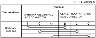
6. Verify that the continuity between antenna feeder No.3 terminals is as indicated in the table.
-
• If not as indicated in the table, replace antenna feeder No.3.
With center display
1. Disconnect the negative battery cable. (See NEGATIVE BATTERY CABLE DISCONNECTION/CONNECTION [SKYACTIV-G 2.0, SKYACTIV-G 2.5].) (See NEGATIVE BATTERY CABLE DISCONNECTION/CONNECTION [SKYACTIV-G 2.0, SKYACTIV-G 2.5 (WITHOUT i-stop)].) (See NEGATIVE BATTERY CABLE DISCONNECTION/CONNECTION [SKYACTIV-D 2.2].)
2. Remove the following parts:
- (1) Front scuff plate (See FRONT SCUFF PLATE REMOVAL/INSTALLATION.)
- (2) Rear scuff plate (See REAR SCUFF PLATE REMOVAL/INSTALLATION.)
- (3) B-pillar lower trim (See B-PILLAR LOWER TRIM REMOVAL/INSTALLATION.)
- (4) Front seat belt adjusting cover (See FRONT SEAT BELT REMOVAL/INSTALLATION.)
- (5) Front seat belt upper anchor installation bolt (See FRONT SEAT BELT REMOVAL/INSTALLATION.)
- (6) B-pillar upper trim (See B-PILLAR UPPER TRIM REMOVAL/INSTALLATION.)
- (7) Trunk board (See TRUNK BOARD REMOVAL/INSTALLATION.)
- (8) Trunk end trim (See TRUNK END TRIM REMOVAL/INSTALLATION.)
- (9) Trunk side trim (See TRUNK SIDE TRIM REMOVAL/INSTALLATION.)
- (10) C-pillar trim (See C-PILLAR TRIM REMOVAL/INSTALLATION.)
- (11) Liftgate upper trim (with RDS (radio data system)) (See LIFTGATE UPPER TRIM REMOVAL/INSTALLATION.)
3. Remove the rear passenger's assist handle. (See ASSIST HANDLE REMOVAL/INSTALLATION.)
4. Partially peel back the headliner.
-
Note
-
• If the headliner is peeled back excessively, the headliner could become creased. Be careful not to peel back the headliner excessively.
5. Disconnect antenna feeder No.2.
6. Verify that the continuity between antenna feeder No.3 terminals is as indicated in the table.
-
• If not as indicated in the table, replace antenna feeder No.3.