 |
acxaaw00000386
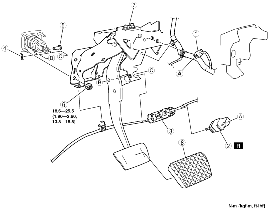
BRAKE PEDAL REMOVAL/INSTALLATION [R.H.D.]
id041100801252
1. Disconnect the brake fluid level sensor connector.
2. Remove the master cylinder reserve tank bracket installation nuts. (See MASTER CYLINDER REMOVAL/INSTALLATION [R.H.D. (MTX)].)(See MASTER CYLINDER REMOVAL/INSTALLATION [R.H.D. (ATX)].)
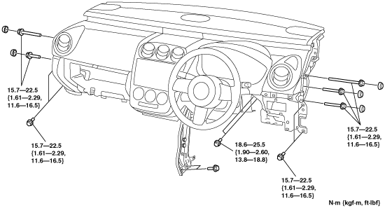
3. Remove in the order indicated in the table.
4. Install in the reverse order of removal.
acxaaw00000386
|
|
1
|
Brake switch connector
|
|
2
|
Brake switch
|
|
3
|
Interlock unit (MTX)
Interlock cable (ATX)
(See INTERLOCK CABLE ADJUSTMENT.)
|
|
4
|
Snap pin
|
|
5
|
Clevis pin
|
|
6
|
Nut
|
|
7
|
Brake pedal
(See Brake Pedal Removal Note.)
|
|
8
|
Pedal pad
|
Brake Pedal Removal Note
1. Remove the console panel. (See CONSOLE PANEL REMOVAL/INSTALLATION.)
2. Remove the console. (See CONSOLE REMOVAL/INSTALLATION.)
3. Remove the front scuff plate inner. (See FRONT SCUFF PLATE REMOVAL/INSTALLATION.)
4. Remove the front side trim. (See FRONT SIDE TRIM REMOVAL/INSTALLATION.)
5. Remove the Glove Compartment. (See GLOVE COMPARTMENT REMOVAL/INSTALLATION.)
6. Remove the dashboard under cover.
7. Remove the bonnet release lever. (See BONNET LATCH AND RELEASE LEVER REMOVAL/INSTALLATION.)
8. Remove the lower panel. (See LOWER PANEL REMOVAL/INSTALLATION.)
9. Remove the a‐pillar lower trim. (See A-PILLAR LOWER TRIM REMOVAL/INSTALLATION.)
10. Remove the a‐pillar trim. (See A-PILLAR TRIM REMOVAL/INSTALLATION.)
11. Remove the dashboard installation bolts and nuts as shown in the figure.
acxaaw00000387
|
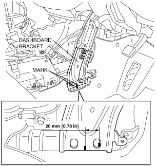
12. Lift up the upper side of the dashboard and move it 20 mm {0.78 in} towards the vehicle rear.
acxaaw00000388
|
13. Move the power brake unit to the vehicle front where the power brake unit fork does not interfere with the brake pedal arm.
14. Remove the brake pedal.
Interlock Unit (MTX) Installation Note
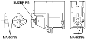
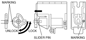
1. Verify that the marking on the slider pin is positioned as shown in the figure.
acxaaw00001189
|
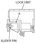
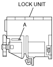
2. Insert the a 1.5mm {0.059 in} round bar or similar into hole A with the slider pin fully pushed in.
acxaaw00001190
|
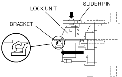
3. With the slider pin pressed, slide the lock unit to fix the lock unit hook into the bracket hole securely as shown in the figure.
acxaaw00001191
|
4. Rotate the slider pin to release the lock and verify that it slides freely.
acxaaw00001192
|
5. Verify that the slider pin contacts the brake pedal stopper rubber and rotate the slider pin to lock.
6. Remove the a 1.5mm {0.059 in} round bar or similar from the lock unit holes A.
acxaaw00001201
|
Brake Switch Installation Note
1. Inspect the brake pedal. (See BRAKE PEDAL INSPECTION [R.H.D.].)
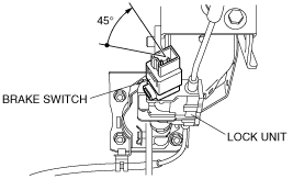
2. With the brake pedal fully released, insert a new brake switch into the installation hole on the lock unit.
3. Secure the brake switch by turning it clockwise 45°.
acxaaw00000389
|
Brake Switch Connector Installation Note
1. Inspect the brake pedal. (See BRAKE PEDAL INSPECTION [R.H.D.].)
2. With the brake pedal in its original position, install the brake switch to the brake switch connector.