 |
ac8wzw00001985
REAR STABILIZER INSTALLATION [4WD]
id0214008042a2
Vehicle Identification Number (VIN): JM0*100001-200000
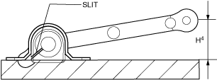
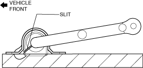
1. Install the rear stabilizer bushing with the slit pointing toward the front of the vehicle.
ac8wzw00001985
|
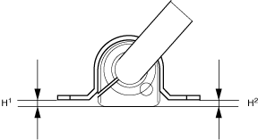
2. During rear stabilizer bracket installation, keep the deviation in the positions of the rear stabilizer bracket and the rear stabilizer bushing within the range shown in the figure. (See Rear Stabilizer Bracket Installation Note.)
ac5wzw00002426
|
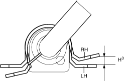
3. After installing the rear stabilizer bracket, verify that the positions of the rear stabilizer bracket and the rear stabilizer bushing are within the range shown in the figure.
ac9uuw00008003
|
4. After installing the rear stabilizer bracket, verify that the right and left-side positions of the rear stabilizer bracket are within the range shown in the figure.
ac9uuw00008004
|
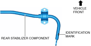
5. Place the rear stabilizer component on a level workbench, and verify that it is within the range shown in the figure.
ac8wzw00001986
|
6. Point the identification mark to the right side of the vehicle and install the rear stabilizer component.
ac8wzw00001987
|
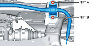
7. Temporarily tighten nuts A and B shown in the figure.
ac8wzw00001988
|
8. Tighten nut A.
9. Tighten nut B.
10. Tighten nut A.
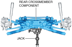
11. Lift up the rear crossmember component using a jack and install the rear crossmember installation nuts.
ac8wzw00001989
|
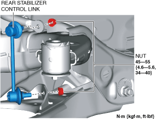
12. Install the following parts. (See Suspension Links Installation Note.)
ac8wzw00001990
|
13. Install the following parts. (See EXHAUST SYSTEM REMOVAL/INSTALLATION [SKYACTIV-G 2.5].) (See EXHAUST SYSTEM REMOVAL/INSTALLATION [SKYACTIV-D 2.2].)
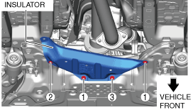
14. Install the insulator.
ac8wzw00001991
|
15. Install the fasteners in the order shown in the figure.
16. Install the following parts. (See FLOOR UNDER COVER REMOVAL/INSTALLATION.)
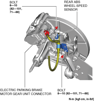
17. Assemble the rear ABS wheel-speed sensor and the electric parking brake motor gear unit connector.
ac8wzw00001992
|
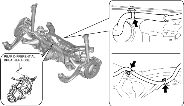
18. Assemble the rear differential breather hose.
ac8wzw00001993
|
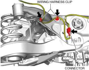
19. Assemble the wiring harness clips and wiring harness connector as shown in the figure.
ac8wzw00001994
|
20. Install the wheel and tire. (See WHEEL AND TIRE REMOVAL/INSTALLATION.)
21. Connect the negative battery terminal. (See NEGATIVE BATTERY TERMINAL DISCONNECTION/CONNECTION.)
22. Inspect the wheel alignment and adjust if necessary. (See REAR WHEEL ALIGNMENT.)
Vehicle Identification Number (VIN): JM0*200001-, PP1*
1. After installing the rear stabilizer bracket, verify that the positions of the rear stabilizer bracket and the rear stabilizer bushing are within the range shown in the figure.
ac9uuw00008003
|
2. Point the identification mark to the right side of the vehicle and install the rear stabilizer component.
ac8wzw00001987
|
3. Temporarily tighten nuts A and B shown in the figure.
ac8wzw00001988
|
4. Tighten nut A.
5. Tighten nut B.
6. Tighten nut A.
7. Lift up the rear crossmember component using a jack and install the rear crossmember installation nuts.
ac8wzw00001989
|
8. Install the following parts. (See Suspension Links Installation Note.)
ac8wzw00001990
|
9. Install the following parts. (See EXHAUST SYSTEM REMOVAL/INSTALLATION [SKYACTIV-G 2.5].) (See EXHAUST SYSTEM REMOVAL/INSTALLATION [SKYACTIV-D 2.2].)
10. Install the insulator.
ac8wzw00001991
|
11. Install the fasteners in the order shown in the figure.
12. Install the following parts. (See FLOOR UNDER COVER REMOVAL/INSTALLATION.)
13. Assemble the rear ABS wheel-speed sensor and the electric parking brake motor gear unit connector.
ac8wzw00001992
|
14. Assemble the rear differential breather hose.
ac8wzw00001993
|
15. Assemble the wiring harness clips and wiring harness connector as shown in the figure.
ac8wzw00001994
|
16. Install the wheel and tire. (See WHEEL AND TIRE REMOVAL/INSTALLATION.)
17. Connect the negative battery terminal. (See NEGATIVE BATTERY TERMINAL DISCONNECTION/CONNECTION.)
18. Inspect the wheel alignment and adjust if necessary. (See REAR WHEEL ALIGNMENT.)
Rear Stabilizer Bracket Installation Note
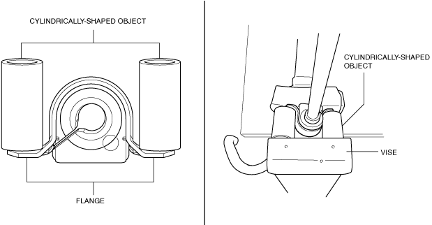
1. If the rear stabilizer bracket cannot be installed, install it using a vise.
ac5uuw00001628
|
Suspension Links Installation Note
1. When installing the joint sections with rubber bushings, perform the following steps.