REAR DIFFERENTIAL REMOVAL/INSTALLATION
id031400146400
Oil and chemical type
|
Silicone sealant
Type: TB1217C or equivalent
|
-
Caution
-
• If the rear ABS wheel-speed sensor wiring harness is pulled by mistake when performing this procedure, it could cause an open circuit. Before servicing, disconnect the rear ABS wheel-speed sensor and set it aside so that the wiring harness will not be pulled by mistake.
• If the characteristic value of a new coupling compartment is not input to the 4WD control module or the characteristic value is input incorrectly after replacing the coupling compartment, it could result in the following conditions:
-
― The system does not operate normally.
― A problem with durability of the coupling compartment occurs.
-
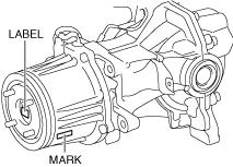
• Read out the characteristic value of the coupling compartment from the label or mark shown in the figure.
-
Note
-
• The characteristic value of the coupling compartment before replacement is stored in the 4WD control module.
• If the characteristic value of a new coupling compartment is not written, it is not stored in the 4WD control module.
1. Switch the ignition ON (engine off).
2. Release the electric parking brake.
3. Switch the ignition off.
4. Disconnect the negative battery terminal. (See NEGATIVE BATTERY TERMINAL DISCONNECTION/CONNECTION.)
5. Remove the wheels and tires. (See WHEEL AND TIRE REMOVAL/INSTALLATION.)
6. Drain the differential oil from the rear differential. (See DIFFERENTIAL OIL REPLACEMENT.)
7. Remove the TWC. (SKYACTIV-G 2.5) (See EXHAUST SYSTEM REMOVAL/INSTALLATION [SKYACTIV-G 2.5].)
8. Remove the middle pipe. (SKYACTIV-D 2.2) (See EXHAUST SYSTEM REMOVAL/INSTALLATION [SKYACTIV-D 2.2].)
9. Remove the propeller shaft. (See PROPELLER SHAFT REMOVAL/INSTALLATION.)
10. Remove the rear drive shaft. (See REAR DRIVE SHAFT REMOVAL/INSTALLATION.)
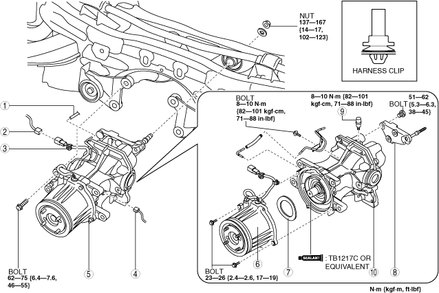
11. Remove in the order shown in the figure.
12. Install in the reverse order of removal.
13. Add the recommended differential oil to the rear differential. (See DIFFERENTIAL OIL REPLACEMENT.)
|
1
|
Hose
|
|
2
|
Connector (4WD solenoid)
|
|
3
|
Harness clip
|
|
4
|
Connector (differential oil temperature sensor)
|
|
5
|
Rear differential component
|
|
6
|
Coupling component
|
|
7
|
Washer
|
|
8
|
Rear differential mounting bracket
|
|
9
|
Breather
|
|
10
|
Rear differential
|
Rear Differential Component Removal Note
-
Warning
-
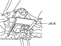
• Always verify that the rear differential component is securely supported by a jack. If the rear differential component falls off, it can cause serious injury or death, and damage to the vehicle.
1. Always verify that the coupling component and rear differential component are securely supported by a jack.
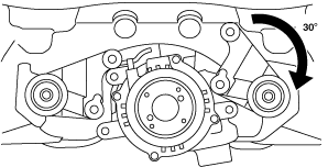
2. Loosen the rear differential mount bracket bolt and rotate the rear differential mount bracket as shown in the figure.
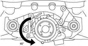
3. Rotate the rear differential as shown in the figure and remove it.
Rear Differential Mount Bracket Installation Note
-
Note
-
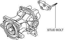
• When loosening the rear differential mount bracket nuts, tighten the rear differential mount bracket stud bolt because it may loosen.
1. Tighten the rear differential mount bracket stud bolt.
-
Tightening torque
-
30—37 N·m {3.1—3.7 kgf·m, 23—27 ft·lbf}
 ac8wzw00002103