CONTROL VALVE BODY REMOVAL/INSTALLATION [GW6A-EL, GW6AX-EL]
id0517i2118000
Replacement part
|
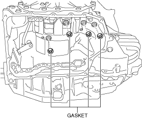
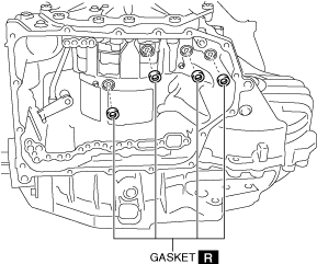
Gasket
Quantity: 4
Location of use: Transaxle case
|
O-ring
Quantity: 2
Location of use: Oil strainer
|
Oil strainer
Quantity: 1
Location of use: Control valve body
|
|
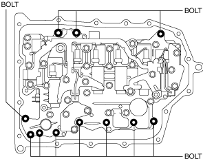
Bolt
Quantity: 16
Location of use: Oil pan
|
Hose clamp
Quantity: 1
Location of use: Control valve body
|
−
|
Oil and chemical type
|
Silicone sealant
Type: TB1217E or equivalent
|
Removal
-
Warning
-
• Do not perform the procedure while the ATF is at a high temperature. Otherwise, it could cause a serious burn.
• Always wear protective eyewear when using the air compressor. If an air compressor is used, dust particles or dirt could spatter and get into the eyes.
-
Caution
-
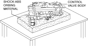
• Placing the control valve body connector side pointed downward could damage the control valve body connector part or sensor. If the servicing can only be performed by pointing the control valve body connector side downward, spread shock-absorbing material, which does not produce dust or foreign matter, and place the control valve body connector part and sensor on the table so that they do not directly contact the table.
1. Shift the selector lever to the P position.
2. Disconnect the negative battery terminal. (See NEGATIVE BATTERY TERMINAL DISCONNECTION/CONNECTION.)
3. Remove front under cover No.2. (See FRONT UNDER COVER No.2 REMOVAL/INSTALLATION.)
4. Clean the outside of the transaxle using steam or a degreaser.
5. Remove the following parts as a single unit. (See INTAKE-AIR SYSTEM REMOVAL/INSTALLATION [SKYACTIV-D 2.2].)
-
• Air cleaner cover
• Air cleaner element
• Fresh-air duct
• Air cleaner case
• Air hose
• Resonance chamber
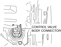
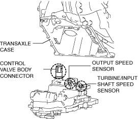
6. Disconnect the control valve body connector.
-
Caution
-
• Be careful that your hand does not touch the terminal as the connector terminal could be damaged.
• Do not allow foreign matter or water to penetrate the connector. Otherwise, it could cause poor contact and corrosion.
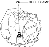
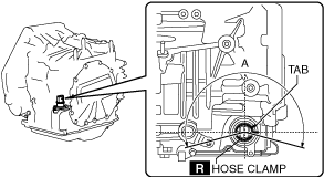
7. Remove the hose clamp.
8. Drain the ATF. (See AUTOMATIC TRANSAXLE FLUID (ATF) REPLACEMENT [GW6A-EL, GW6AX-EL].)
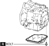
9. Remove the oil pan.
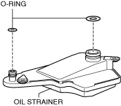
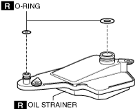
10. Remove the oil strainer.
11. Remove the oil strainer O-ring.
12. Remove the control valve body.
-
Caution
-
• Remove the control valve body directly from underneath so that force is not applied to the control valve body connector in the lateral direction.
13. Remove the oil seal (control valve body). (See OIL SEAL (CONTROL VALVE BODY) REPLACEMENT [GW6A-EL, GW6AX-EL].)
14. Remove the gaskets from the transaxle case.
Installation
1. Install the gaskets to the transaxle case.
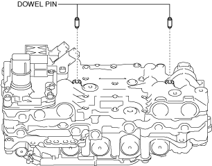
2. Install the dowel pins to the control valve body.
-
Note
-
• Oil with a color different from the genuine ATF may get in the new control valve body.
• If the dowel pins remain in the transaxle case, remove the dowel pins from the transaxle case and install them to the control valve body.
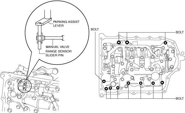
3. Install the control valve body so that the parking assist lever component is engaged on both surfaces of the manual valve.
-
Caution
-
• Install the control valve body so that the turbine/input shaft speed sensor, output speed sensor, and control valve body connector do not contact the transaxle case.
-
Tightening torque
-
9—10 N·m {92—101 kgf·cm, 80—88 in·lbf}
4. Move the manual valve in both directions of the arrow and verify that the manual valve is correctly connected to the parking assist lever component.
-
Note
-
• If the manual valve can only move within the allowable area of play on both surfaces of the parking assist lever component and the manual valve, the manual valve and the parking assist lever component are engaged correctly.
5. Install the new oil strainer O-ring.
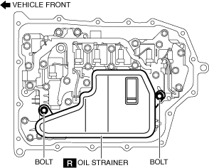
6. Install the new oil strainer.
-
Tightening torque
-
9—10 N·m {92—101 kgf·cm, 80—88 in·lbf}
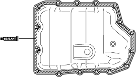
7. Apply silicone sealant TB1217E or equivalent to the contact surface of the oil pan.
-
Caution
-
• Clean any remaining silicone sealant on the contact surface of the transaxle case and oil pan, and degrease the sealant area. Otherwise, oil could leak.
8. Install the oil pan using a new bolt before the applied sealant starts to harden.
-
Tightening torque
-
8—10 N·m {82—101 kgf·cm, 71—88 in·lbf}
9. Install front under cover No.2. (See FRONT UNDER COVER No.2 REMOVAL/INSTALLATION.)
10. Install the oil seal (control valve body). (See OIL SEAL (CONTROL VALVE BODY) REPLACEMENT [GW6A-EL, GW6AX-EL].)
11. Install the new hose clamp to the position shown in the figure.
-
Caution
-
• If a hose clamp is reused it could cause ATF leakage, therefore use a new hose clamp.
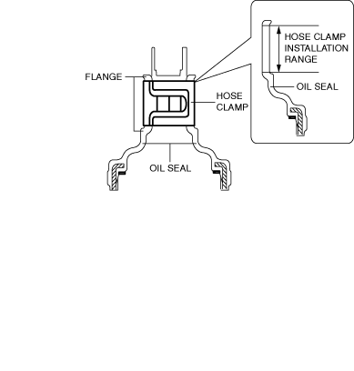
• Install the hose clamp tab to within the range shown in the figure.
A: 210°
• Install the hose clamp so that it does not interfere with the top and bottom flanges of the oil seal to maintain the waterproofing integrity.
12. Connect the control valve body connector.
-
Caution
-
• Be careful that your hand does not touch the terminal as the connector terminal could be damaged.
• Verify that there is no fluid or foreign matter adhering to the connector before connecting the connector.
• Insert the connector straight as the connector terminal could be damaged.
• Rotate the connector lever until a click is heard.
13. Add ATF. (See AUTOMATIC TRANSAXLE FLUID (ATF) REPLACEMENT [GW6A-EL, GW6AX-EL].)
14. Install the following parts as a single unit. (See INTAKE-AIR SYSTEM REMOVAL/INSTALLATION [SKYACTIV-D 2.2].)
-
• Air cleaner cover
• Air cleaner element
• Fresh-air duct
• Air cleaner case
• Air hose
• Resonance chamber
15. Connect the negative battery terminal. (See NEGATIVE BATTERY TERMINAL DISCONNECTION/CONNECTION.)
16. Perform TCM configuration. (Control valve body replacement) (See TCM CONFIGURATION [GW6A-EL, GW6AX-EL].)
-
Caution
-
• The transaxle does not operate normally if the TCM configuration is not performed. When the control valve body is replaced, always perform the TCM configuration to enable the transaxle to operate normally.
• When the control valve body is replaced, a U-code DTC is output. After completing the TCM configuration, clear the U-code DTC and verify that no DTCs are output.
17. Delete the U code DTC and verify that no DTC is output. (See ON-BOARD DIAGNOSTIC SYSTEM DTC INSPECTION [TCM (GW6A-EL, GW6AX-EL)].)
18. Perform the initial learning. (Control valve body replacement) (See INITIAL LEARNING [GW6A-EL, GW6AX-EL].)
19. Perform the mechanical system test. (See MECHANICAL SYSTEM TEST [GW6A-EL, GW6AX-EL].)
20. Perform the road test. (See ROAD TEST [GW6A-EL, GW6AX-EL].)