DTC U3003:16, U3003:17, U3006:16, U3006:17 [CLIMATE CONTROL UNIT (FULL-AUTO AIR CONDITIONER)]
id0702k2902500
System malfunction location |
• U3003:16: Front climate control unit power supply circuit voltage below threshold (10 V or less)
• U3003:17: Front climate control unit power supply circuit voltage above threshold (17.3 V or more)
• U3006:16: Rear climate control unit power supply circuit voltage below threshold (10 V or less)
• U3006:17: Rear climate control unit power supply circuit voltage above threshold (17.3 V or more)
|
---|---|
Detection condition
|
• Front climate control unit power supply voltage is other than 10.1—17.2 V
• Rear climate control unit power supply voltage is other than 10.1—17.2 V
|
Fail-safe function
|
Not applicable
|
Possible cause
|
• DTCs stored in PCM.
• Battery malfunction
• Generator system malfunction
• Front climate control unit connector or terminal malfunction
• Rear climate control unit connector or terminal malfunction
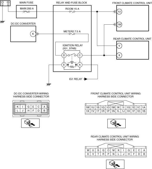
• MAIN 200 A fuse malfunction
• ROOM 15 A fuse malfunction
• METER2 7.5 A fuse malfunction
• Ignition relay (IG1_STAB) malfunction
• Short to ground in wiring harness between front climate control unit terminal 1U — ROOM 15 A fuse
• Short to ground in wiring harness between rear climate control unit terminal V — ROOM 15 A fuse
• Open circuit in wiring harness between front climate control unit terminal 1U — positive battery terminal
• Open circuit in wiring harness between rear climate control unit terminal V — positive battery terminal
• Open circuit in wiring harness between front climate control unit terminal 1W — DC-DC converter terminal K
• Open circuit in wiring harness between rear climate control unit terminal X — DC-DC converter terminal K
• Short to ground in wiring harness between front climate control unit terminal 1W — MAIN 200 A fuse
• Short to ground in wiring harness between rear climate control unit terminal X — MAIN 200 A fuse
• Front climate control unit malfunction
• Rear climate control unit malfunction
|
![]() |
Diagnostic procedure
STEP |
INSPECTION |
ACTION |
|
---|---|---|---|
1
|
INSPECT IGNITION RELAY (IG1_STAB) FOR MALFUNCTION
• Switch the ignition off.
• Disconnect the negative battery terminal.
• Remove the ignition relay (IG1_STAB).
(See RELAY LOCATION.)
• Inspect the ignition relay (IG1_STAB).
(See RELAY INSPECTION.)
• Is the ignition relay (IG1_STAB) normal?
|
Yes
|
Go to the next step.
|
No
|
Replace the ignition relay (IG1_STAB), then go to Step 8.
(See RELAY LOCATION.)
|
||
2
|
PERFORM PCM DTC INSPECTION
• Perform the PCM DTC inspection using the M-MDS.
• Are any DTCs present?
|
Yes
|
Go to the applicable DTC inspection.
|
No
|
Go to the next step.
|
||
3
|
INSPECT BATTERY
• Inspect the battery.
(See BATTERY INSPECTION.)
• Is the battery normal?
|
Yes
|
Go to the next step.
|
No
|
Replace or charge the battery.
(See BATTERY RECHARGING.)
Then go to Step 8.
|
||
4
|
INSPECT GENERATOR
• Inspect the generator.
• Is the generator normal?
|
Yes
|
Go to the next step.
|
No
|
Replace or charge the generator.
Then go to Step 8.
|
||
5
|
VERIFY CLIMATE CONTROL UNIT CONNECTOR CONDITION
• Disconnect the climate control unit connector.
(See FRONT FRONT CLIMATE CONTROL UNIT REMOVAL/INSTALLATION.)
• Inspect the connector and terminals (corrosion, damage, pin disconnection).
• Are the connector and terminals normal?
|
Yes
|
Go to the next step.
|
No
|
Repair/replace the connector or terminal.
After repair procedure, go to Step 8.
|
||
6
|
INSPECT CLIMATE CONTROL UNIT POWER SUPPLY VOLTAGE
• Climate control unit connector is disconnected.
• Connect the negative battery terminal.
• Switch the ignition ON (engine off or on).
• Measure the voltage at the following terminals (wiring harness-side):
• Is the voltage 10.1—17.2 V?
|
Yes
|
Go to the next step.
|
No
|
Inspect the ROOM 15 A fuse and MAIN 200 A fuse.
• If the fuse is blown:
• If the fuse is damaged:
• If the fuse is normal:
Then go to Step 8.
|
||
7
|
INSPECT CLIMATE CONTROL UNIT POWER SUPPLY VOLTAGE
• Climate control unit connector is disconnected.
• Measure the voltage at the following terminals (wiring harness-side):
• Is the voltage 10.1—17.2 V?
|
Yes
|
Go to the next step.
|
No
|
Inspect the METER2 7.5 A fuse.
• If the fuse is blown:
• If the fuse is damaged:
• If the fuse is normal:
Then go to the next step.
|
||
8
|
VERIFY THAT SAME DTC IS NOT OUTPUT AGAIN
• Switch the ignition off.
• Disconnect the negative battery terminal.
• Reconnect the disconnected connectors.
• Connect the negative battery terminal.
• Clear the DTC from the climate control unit memory using the M-MDS.
• Perform the DTC inspection for the climate control unit using the M-MDS.
• Is the same DTC displayed?
|
Yes
|
Repeat the inspection from Step 1.
• If the malfunction recurs, replace the climate control unit.
Go to the next step.
|
No
|
Go to the next step.
|
||
9
|
VERIFY THAT NO OTHER DTCs ARE PRESENT
• Verify other DTCs displayed.
• Are any other DTCs displayed?
|
Yes
|
Repair or replace the malfunctioning part according to the applicable DTC troubleshooting.
|
No
|
DTC troubleshooting completed.
|