 |
ac8wzw00002195
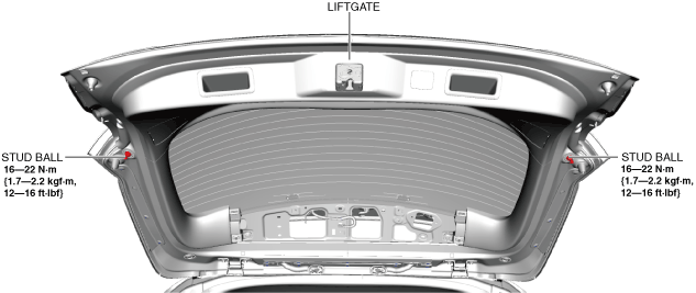
LIFTGATE REMOVAL/INSTALLATION
id091100521200
Replacement part
|
Inner liftgate grommet
Quantity: 2
Location of use: Liftgate grommet
|
Clip
Quantity: 10
Location of use: Weatherstrip
|
1. Disconnect the negative battery terminal. (See NEGATIVE BATTERY TERMINAL DISCONNECTION/CONNECTION.)
2. Remove the liftgate upper trim. (See LIFTGATE UPPER TRIM REMOVAL/INSTALLATION.)
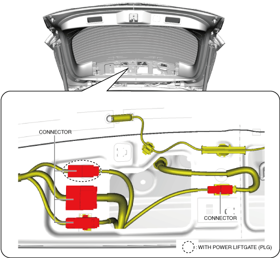
3. Disconnect the connectors.
ac8wzw00002195
|
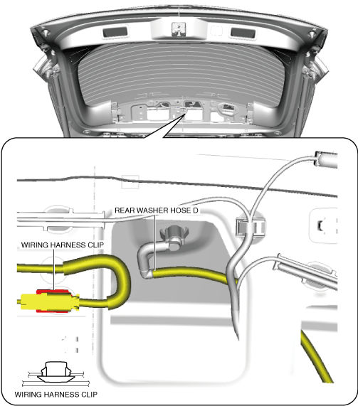
4. Remove the wiring harness clip.
ac8wzw00002196
|
5. Disconnect rear washer hose D.
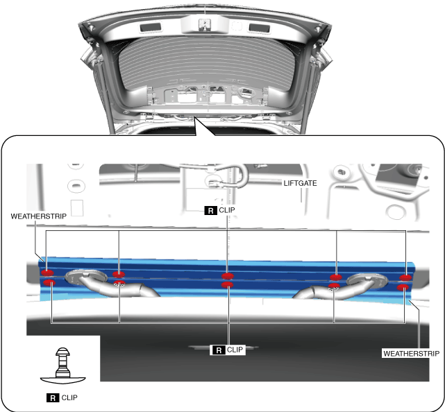
6. Remove the clips.
ac8wzw00003169
|
7. Remove the weatherstrip.
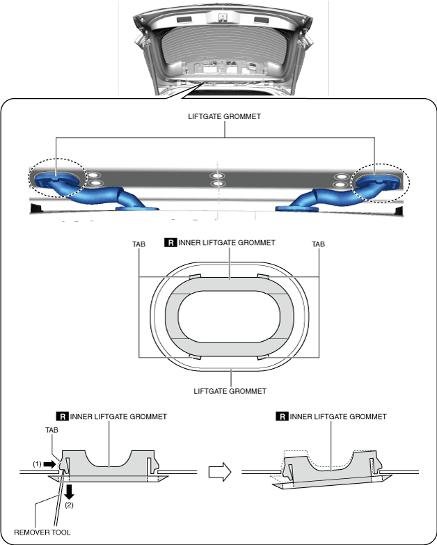
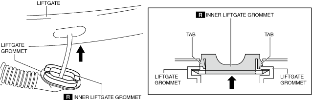
8. Move the liftgate grommets in the directions of the arrows shown in the figure, and remove the liftgate grommets from the inner liftgate grommets.
ac8wzw00002198
|
9. Using a remover tool, remove the inner liftgate grommet from the liftgate while pressing the tabs of the inner liftgate grommet in the order of arrows (1) and (2) shown in the figure. (See Liftgate Grommet Installation Note.)
ac8wzw00002199
|
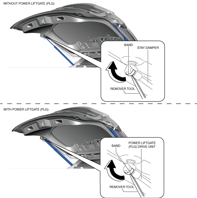
10. Insert the remover tool into the position shown in the figure.
11. Move the remover tool in the direction of the arrow shown in the figure, remove the stay damper securing band (without power liftgate (PLG)) or the power liftgate drive unit securing band (with power liftgate (PLG)).
ac8wzw00002200
|
12. Remove the bolts.
ac8wzw00003495
|
13. Remove the liftgate.
14. Remove the stud balls. (Only when replacing stud balls)
ac8wzw00002202
|
15. Install in the reverse order of removal.
16. Adjust the liftgate. (See LIFTGATE ADJUSTMENT.)
17. Perform 360° view monitor system aiming. (with 360° view monitor system) (See 360°VIEW MONITOR SYSTEM AIMING.)
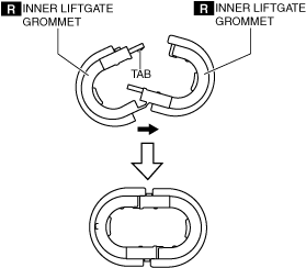
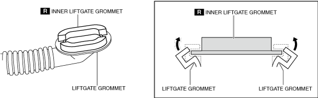
Liftgate Grommet Installation Note
1. Install the liftgate grommet using the following procedure.
ac8wzw00004107
|
ac8wzw00002204
|
ac8wzw00002205
|