Note
• Cut the floor covering to use the service hole.
ac8wzw00000549
|
FUEL GAUGE SENDER UNIT REMOVAL/INSTALLATION [4WD]
id092200012002
Replacement part
|
Packing
Quantity: 1
Location of use: Fuel gauge sender unit (main (SKYACTIV-D 2.2))
|
Fuel gauge sender unit (sub)
Quantity: 1
Location of use: Fuel tank
|
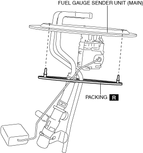
Fuel Gauge Sender Unit (Main)
SKYACTIV-G 2.5
SKYACTIV-D 2.2
1. Perform the [Fuel Line Safety Procedure] referring to the [BEFORE REPAIR PROCEDURE]. (See BEFORE SERVICE PRECAUTION [SKYACTIV-D 2.2].)
2. Using the following procedure:
3. Remove the second-row seat. (See SECOND-ROW SEAT REMOVAL/INSTALLATION.)
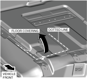
4. Cut the floor covering along the dotted lines shown in the figure and partially peel it back.
ac8wzw00000549
|
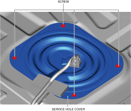
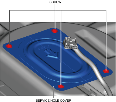
5. Remove the screws.
ac8wzw00000550
|
6. Remove the service hole cover.
7. While pressing the tabs of clip A in the direction of arrows (1) shown in the figure, pull clip A in the direction of arrow (2) to detach the tabs of clip A from the fuel gauge sender unit (main).
ac8wzw00000551
|
8. Detach clip A.
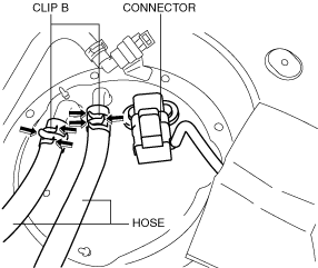
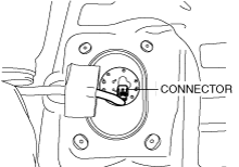
9. Disconnect the connector.
ac8wzw00000552
|
10. Disconnect the hose from the fuel gauge sender unit (main) while pressing the tabs of clips B in the direction of the arrows shown in the figure.
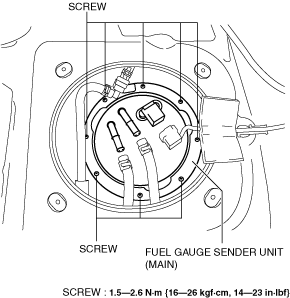
11. Remove the screws.
ac8wzw00000553
|
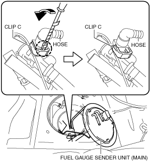
12. Insert a tape-wrapped flathead screwdriver into the gap between clip C and the hose shown in the figure.
ac8wzw00000554
|
13. Move the flathead screwdriver in the direction of the arrow shown in the figure to detach clip C from the hose.
14. Disconnect the hose.
15. Remove the fuel gauge sender unit (main).
16. Remove the packing.
ac8wzw00000555
|
17. Install in the reverse order of removal.
18. Perform the fuel leakage inspection referring to [AFTER SERVICE PRECAUTION]. (See AFTER SERVICE PRECAUTION [SKYACTIV-D 2.2].)
Fuel Gauge Sender Unit (Sub)
1. Perform the [Fuel Line Safety Procedure] referring to the [BEFORE REPAIR PROCEDURE]. (See BEFORE SERVICE PRECAUTION [SKYACTIV-G 2.5].) (See BEFORE SERVICE PRECAUTION [SKYACTIV-D 2.2].)
2. Remove the second-row seat. (See SECOND-ROW SEAT REMOVAL/INSTALLATION.)
3. Remove the rear scuff plate. (See REAR SCUFF PLATE REMOVAL/INSTALLATION.)
4. Cut the floor covering along the dotted lines shown in the figure and partially peel it back.
ac8wzw00000556
|
5. Remove the screws.
ac8wzw00000557
|
6. Remove the service hole cover.
7. Disconnect the connector.
ac8wzw00000558
|
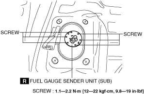
8. Remove the screws.
ac8wzw00000559
|
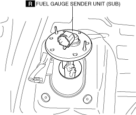
9. Remove the fuel gauge sender unit (sub).
ac8wzw00000560
|
10. Install in the reverse order of removal.
11. Perform the fuel leakage inspection referring to [AFTER SERVICE PRECAUTION]. (See AFTER SERVICE PRECAUTION [SKYACTIV-G 2.5].) (See AFTER SERVICE PRECAUTION [SKYACTIV-D 2.2].)