|
ac9uuw00002099
PID/DATA MONITOR INSPECTION [AW6A-EL, AW6AX-EL]
id0502j7805600
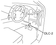
1. Connect the M-MDS to the DLC-2.
L.H.D.
ac9uuw00002099
|
R.H.D.
ac9wzw00000008
|
2. After the vehicle is identified, select the following items from the initialization screen of the M-MDS.
3. Select the applicable PID from the PID table.
4. Verify the PID data according to the directions on the screen.
PID/DATA MONITOR AND RECORD function table
|
Monitor item |
Unit/Condition |
Condition/Specification |
Action |
TCM terminal |
|---|---|---|---|---|
|
BOO TCM
|
On/Off
|
• Brake pedal depressed: On
• Other: Off
|
Inspect the brake switch.
(See BRAKE SWITCH INSPECTION.)
|
N/A
|
|
DTCCNT
|
N/A
|
Indicates number of DTC
|
Check DTC.
|
N/A
|
|
DWN SW
|
On/Off
|
• Down shift at M range: On
• Other: Off
|
Inspect the selector lever component.
|
A4
|
|
ECT TCM
|
°C, °F
|
Indicates ECT
|
Inspect the PCM.
(See PCM INSPECTION [MZI-3.7].)
|
N/A
|
|
FDPDTC
|
N/A
|
Indicates code of FREEZE FRAME DATA
|
Inspect the TCM.
|
N/A
|
|
GEAR_RA
|
N/A
|
• 1GR: 4.148
• 2GR: 2.370
• 3GR: 1.555
• 4GR: 1.154
• 5GR: 0.859
• 6GR: 0.685
|
Inspect following PIDs: THOP, TSS, VSS
|
N/A
|
|
GEAR_SEL
|
1st/2nd/3rd/4th/5th/6th
|
• 1GR: 1st
• 2GR: 2nd
• 3GR: 3rd
• 4GR: 4th
• 5GR: 5th
• 6GR: 6th
|
Inspect following PIDs: THOP, TSS, VSS
|
N/A
|
|
LPS
|
A
|
100—1,000 mA
|
Inspect the pressure control solenoid.
|
B1, B3
|
|
MNL SW
|
On/Off
|
• M range: On
• Other: Off
|
Inspect the selector lever component.
|
A7
|
|
OSS
|
RPM
|
• Ignition switch ON:0 RPM
• Indicates output shaft speed
|
Inspect the VSS.
|
B19, B20
|
|
PNP_TCM
|
Drive/Neutral
|
• P, N position: Neutral
• D, M range or R position: Drive
|
Inspect the TR switch.
|
N/A
|
|
RPM TCM
|
RPM
|
• Ignition switch ON:0 RPM
• Idle:700—800 RPM
|
Inspect the PCM.
(See PCM INSPECTION [MZI-3.7].)
|
N/A
|
|
SSC
|
A
|
• P, R, N position or D/M range (5GR, 6GR): solenoid on
• Other: solenoid off
|
Inspect the shift solenoid C.
|
B10, B11
|
|
SSD
|
A
|
• P, R, N position or D/M range (1GR, 2GR, 3GR): solenoid on
• Other: solenoid off
|
Inspect the shift solenoid D.
|
B17, B18
|
|
SSE
|
A
|
• R position (more than 11 km/h {4 mph}) or D/M range (1GR, 2GR, 4GR, 6GR): solenoid on
• Other: solenoid off
|
Inspect the shift solenoid E.
|
B14, B22
|
|
SSF
|
A
|
• P, R, N position or D/M range (1GR, 3GR, 4GR, 5GR): solenoid on
• Other: solenoid off
|
Inspect the shift solenoid F.
|
B16, B21
|
|
TCCC
|
A
|
• TCC on: solenoid on
• Other: solenoid off
|
Inspect the TCC control solenoid.
|
B4, B9
|
|
TFT
|
°C, °F
|
Indicates ATF temperature
|
Inspect the TFT sensor.
|
B7, B8
|
|
TFTV
|
V
|
• ATF temperature 10 °C {50 °F}:4.78—4.81 V
• ATF temperature 25 °C {77 °F}:4.61—4.65 V
• ATF temperature 110 °C {230 °F}:2.30—2.45 V
|
Inspect the TFT sensor.
|
B7, B8
|
|
THOP
|
%
|
• CTP: 0%
• WOT: 100%
|
Inspect the PCM.
(See PCM INSPECTION [MZI-3.7].)
|
N/A
|
|
TR
|
R/N/D/P
|
• R position: R
• N position: N
• D range: D
• P position: P
|
Inspect the TR switch.
|
N/A
|
|
TRD
|
On/Off
|
• D range: On
• Other ranges and all positions: Off
|
Inspect the TR switch.
|
N/A
|
|
TRR
|
On/Off
|
• R position: On
• Other positions and all ranges: Off
|
Inspect the TR switch.
|
N/A
|
|
TSS
|
RPM
|
• Ignition switch ON:0 RPM
• Idle:700—800 RPM
|
Inspect the input/turbine speed sensor.
|
N/A
|
|
UP SW
|
On/Off
|
• Up shift at M range: On
• Other: Off
|
Inspect the selector lever component.
|
A3
|
|
VSS
|
KPH, MPH
|
Indicates vehicle speed
|
Inspect the VSS.
|
N/A
|
Simulation Function Procedure
1. Connect the M-MDS to the DLC-2.
L.H.D.
ac9uuw00002099
|
R.H.D.
ac9wzw00000008
|
2. After the vehicle is identified, select the following items from the initialization screen of the M-MDS.
3. Select the active command modes from the PID table.
4. Perform the active command modes, inspect the operations for each parts.
Simulation item table
|
Simulation item |
Applicable component |
Unit/Condition |
Test condition |
TCM terminal |
|---|---|---|---|---|
|
LPS
|
Pressure control solenoid
|
A
|
Ignition switch ON position (engine off) or idle
|
B1, B3
|
|
SSA
|
Shift solenoid A
|
On/Off
|
Ignition switch ON position (engine off) or idle
|
B5
|
|
SSB
|
Shift solenoid B
|
On/Off
|
Ignition switch ON position (engine off) or idle
|
B2
|
|
SSC
|
Shift solenoid C
|
A
|
Ignition switch ON position (engine off) or idle
|
B10, B11
|
|
SSD
|
Shift solenoid D
|
A
|
Ignition switch ON position (engine off) or idle
|
B17, B18
|
|
SSE
|
Shift solenoid E
|
A
|
Ignition switch ON position (engine off) or idle
|
B14, B22
|
|
SSF
|
Shift solenoid F
|
A
|
Ignition switch ON position (engine off) or idle
|
B16, B21
|