 |
ac9uuw00004120
INPUT/TURBINE SPEED SENSOR REMOVAL/INSTALLATION [AY6A-EL, AY6AX-EL]
id0517k3298400
1. Disconnect the negative battery cable.
2. Remove the fresh-air duct and air cleaner component as a single unit. (See INTAKE-AIR SYSTEM REMOVAL/INSTALLATION [MZI-3.7].)
3. Remove the air cleaner bracket. (See INTAKE-AIR SYSTEM REMOVAL/INSTALLATION [MZI-3.7].)
4. Clean the transaxle exterior throughout with a steam cleaner or cleaning solvents.
5. Drain the ATF. (See AUTOMATIC TRANSAXLE FLUID (ATF) REPLACEMENT [AY6A-EL, AY6AX-EL].)
6. Disconnect the oil hose from the oil cooler. (See OIL COOLER REMOVAL/INSTALLATION [AY6A-EL, AY6AX-EL].)
7. Disconnect the oil cooler from the transaxle with the water hose connected, and set it out of the way. (See OIL COOLER REMOVAL/INSTALLATION [AY6A-EL, AY6AX-EL].)
8. Disconnect the oil hose from the oil pipe component (transaxle side). (See OIL COOLER REMOVAL/INSTALLATION [AY6A-EL, AY6AX-EL].)
9. Remove the oil pipe component (transaxle side). (See OIL COOLER REMOVAL/INSTALLATION [AY6A-EL, AY6AX-EL].)
10. Remove the control valve body cover. (See CONTROL VALVE BODY COVER REPLACEMENT [AY6A-EL, AY6AX-EL].)
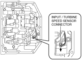
11. Disconnect the input/turbine speed sensor connector.
ac9uuw00004120
|
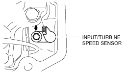
12. Remove the input/turbine speed sensor.
am6xuw00004051
|
13. Install the input/turbine speed sensor.
am6xuw00004051
|
14. Connect the input/turbine speed sensor connector.
ac9uuw00004120
|
15. Install the new control valve body cover. (See CONTROL VALVE BODY COVER REPLACEMENT [AY6A-EL, AY6AX-EL].)
16. Install the oil pipe component (transaxle side). (See OIL COOLER REMOVAL/INSTALLATION [AY6A-EL, AY6AX-EL].)
17. Connect the oil hose to the oil pipe component (transaxle side). (See OIL COOLER REMOVAL/INSTALLATION [AY6A-EL, AY6AX-EL].)
18. Install the oil cooler to the transaxle. (See OIL COOLER REMOVAL/INSTALLATION [AY6A-EL, AY6AX-EL].)
19. Connect the oil hose to the oil cooler. (See OIL COOLER REMOVAL/INSTALLATION [AY6A-EL, AY6AX-EL].)
20. Install the air cleaner bracket. (See INTAKE-AIR SYSTEM REMOVAL/INSTALLATION [MZI-3.7].)
21. Add ATF. (See AUTOMATIC TRANSAXLE FLUID (ATF) LEVEL ADJUSTMENT [AY6A-EL, AY6AX-EL].)
22. Install the fresh-air duct and air cleaner component as a single unit. (See INTAKE-AIR SYSTEM REMOVAL/INSTALLATION [MZI-3.7].)
23. Connect the negative battery cable.
24. Adjust the ATF level. (See AUTOMATIC TRANSAXLE FLUID (ATF) LEVEL ADJUSTMENT [AY6A-EL, AY6AX-EL].)
25. Perform the “MECHANICAL SYSTEM TEST“. (See MECHANICAL SYSTEM TEST [AY6A-EL, AY6AX-EL].)