 |
ac9uuw00002733
VEHICLE SPEED SENSOR (VSS) INSPECTION [AW6AX-EL]
id0517j6801400
On-Vehicle Inspection
1. Disconnect the negative battery cable.
2. Remove the air cleaner component. (See INTAKE-AIR SYSTEM REMOVAL/INSTALLATION [MZI-3.7].)
3. Remove the TCM. (See TCM REMOVAL/INSTALLATION [AW6AX-EL].)
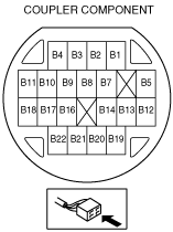
4. Verify that there is no continuity between the coupler component terminals B19 and GND or B20 and GND.
ac9uuw00002733
|
ac9uuw00002734
|
5. Verify that there is continuity between coupler component terminals B19 and B20.
ac9uuw00002733
|
ac9uuw00002734
|
6. Install the TCM. (See TCM REMOVAL/INSTALLATION [AW6AX-EL].)
7. Install the air cleaner component. (See INTAKE-AIR SYSTEM REMOVAL/INSTALLATION [MZI-3.7].)
8. Connect the negative battery cable.
Off-Vehicle Inspection
1. Disconnect the negative battery cable.
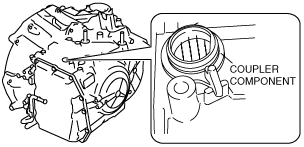
2. Remove the VSS. (See VEHICLE SPEED SENSOR (VSS) REMOVAL/INSTALLATION [AW6AX-EL].)
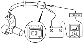
3. Connect the VSS terminal 2 to the battery positive terminal, connect the battery negative terminal to VSS terminal 1 through an ammeter set to a resistance of 100 ohm.
ac9uuw00001961
|
4. Measure the current while waving a magnet back and forth over the top of the VSS (less than 5 mm {0.197 in}).
ac9uuw00001962
|
VSS
|
Signal |
Current (mA) |
|---|---|
|
High
|
12.0—16.0
|
|
Low
|
4.0—8.0
|
5. Install the VSS. (See VEHICLE SPEED SENSOR (VSS) REMOVAL/INSTALLATION [AW6AX-EL].)
6. Connect the negative battery cable.
7. Perform the mechanical system test. (See MECHANICAL SYSTEM TEST [AW6AX-EL].)