|
ac9wzw00000627
AUTOMATIC TRANSAXLE REMOVAL/INSTALLATION [AW6AX-EL]
id0517j6802400
1. Disconnect the negative battery cable.
2. Remove the following parts.
3. Drain the ATF. (See AUTOMATIC TRANSAXLE FLUID (ATF) REPLACEMENT [AW6AX-EL].)
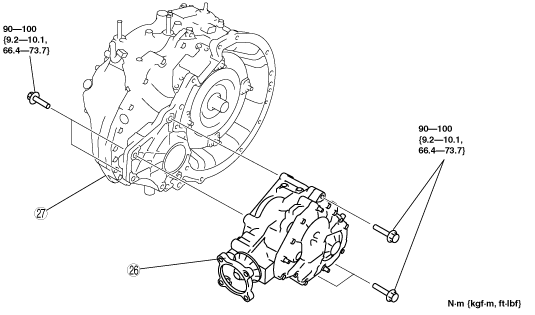
4. Remove in the order shown in the figure.
5. Install in the reverse order of removal.
6. Add ATF to the specified level. (See AUTOMATIC TRANSAXLE FLUID (ATF) REPLACEMENT [AW6AX-EL].)
7. Perform the mechanical system test. (See MECHANICAL SYSTEM TEST [AW6AX-EL].)
|
Service item |
Test item |
|||
|---|---|---|---|---|
|
Line pressure test |
Stall test |
Time lag test |
Time lag test |
|
|
ATX replacement
|
X
|
|
|
|
|
ATX overhaul
|
X
|
X
|
X
|
X
|
|
Torque converter replacement
|
X
|
X
|
|
|
|
Oil pump replacement
|
X
|
|
|
|
|
Control valve body component
|
X
|
|
|
|
|
Clutch system replacement
|
X
|
|
X
|
X
|
ac9wzw00000627
|
|
1
|
TCM connector
|
|
2
|
Ground
|
|
3
|
Wiring harness bracket
|
|
4
|
Selector cable
|
|
5
|
Transaxle mounting bolt (Upper side)
|
|
6
|
Steering shaft
|
|
7
|
Stabilizer control link
|
|
8
|
Tie-rod end ball joint
|
|
9
|
Lower arm ball joint
|
|
10
|
No.1 engine mount
|
|
11
|
Transverse member
|
|
12
|
Crossmember bracket
|
|
13
|
Crossmember
|
|
14
|
Drive shaft
|
|
15
|
Joint shaft
|
|
16
|
Transfer bracket
|
|
17
|
Oil hose
|
|
18
|
Oil cooler
|
|
19
|
Starter
|
|
20
|
Heater pipe
|
|
21
|
Torque converter installation nuts
|
|
22
|
No.4 engine mount bracket
|
|
23
|
Transaxle mounting bolt (lower side)
|
|
24
|
Transaxle and transfer
|
|
25
|
Oil filter tube, Dipstick, breather hose
|
TRANSAXLE AND TRANSFER
ac9wzw00000012
|
|
26
|
Transfer
|
|
27
|
Transaxle
|
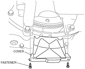
Torque Converter Nuts Removal Note
1. Remove the cover as shown in the figure.
ac9uuw00001612
|
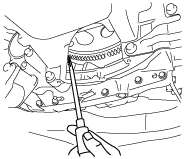
2. Align the holes by turning the torque converter.
3. Insert a flathead screwdriver through the converter housing service hole, and lock the drive plate.
ac9uuw00001656
|
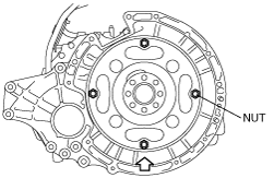
4. Remove the torque converter nuts.
ac9uuw00001668
|
No.1 Engine Mount Removal Note
1. Remove the No.1 engine mounting bracket bolts.
ac9wzw00000697
|
2. Remove the No.1 engine mount, No.1 engine mount bracket and the front crossmember as a single unit. (See FRONT CROSSMEMBER REMOVAL/INSTALLATION [L.H.D.].) (See FRONT CROSSMEMBER REMOVAL/INSTALLATION [R.H.D.].)
ac9wzw00000786
|
No.4 Engine Mount Bracket Removal Note
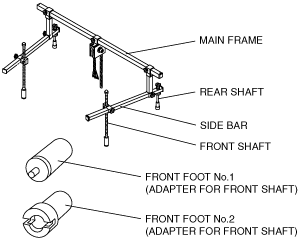
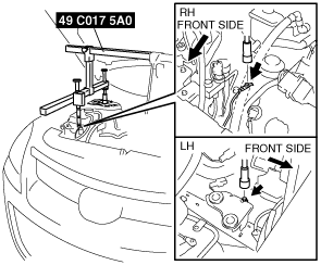
1. Install the SST using the following procedure.
ac9uuw00001980
|
ac9uuw00001981
|
ac9uuw00001982
|
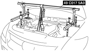
2. Support the engine using the SSTs.
ac9wzw00000661
|
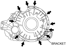
3. Remove the No.4 engine mount bracket.
Transaxle and Transfer Removal Note
1. Support the transaxle and transfer on a jack.
ac9uuw00001983
|
2. Remove the transaxle mounting bolts.
3. Remove the transaxle and transfer.
Transaxle and Transfer Installation Note
1. Set the transaxle and transfer on a jack and lift it.
2. Rotate the drive plate so that the logo mark faces upward.
ac9uuw00001671
|
3. Rotate the torque converter so that the mark faces upward.
ac9uuw00001672
|
4. Install the transaxle mounting bolts and bracket.
ac9uuw00001669
|
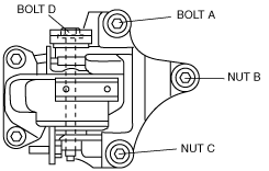
No.4 Engine Mount Bracket Installation Note
1. Install the No.4 engine mount bracket to the transaxle and temporarily tighten nuts.
ac9uuw00001984
|
2. Temporarily tighten bolt.
3. Temporarily tighten bolt A and nuts B, C.
4. Tighten bolt A, nuts B and C in the order of B→A→C.
5. Tighten bolt D.
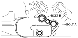
No.1 Engine Mount Installation Note
1. Install the No.1 engine mount, No.1 engine mount bracket and the front crossmember as a single unit. (See FRONT CROSSMEMBER REMOVAL/INSTALLATION [L.H.D.].) (See FRONT CROSSMEMBER REMOVAL/INSTALLATION [R.H.D.].)
ac9wzw00000786
|
2. Tighten the No.1 engine mount bracket bolt A and B in order of A→B.
ac9wzw00000787
|
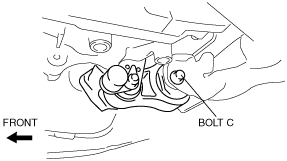
3. Tighten the No.1 engine mount bolt C at the specified torque.
ac9uuw00003036
|
Torque Converter Nuts Installation Note
1. Align the holes by turning the torque converter.
2. Insert a screwdriver through the converter housing service hole, and lock the drive plate.
ac9uuw00001657
|
3. Tighten the torque converter mounting nuts.
ac9uuw00001668
|
4. Install the cover as shown in the figure.
ac9uuw00001612
|
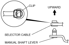
Selector Cable Installation Note
1. Install the selector lever to the manual shaft lever so that no load acts on the selector cable.
ac9uuw00001985
|
2. Confirm that the tip of the manual shaft lever projects out of the end of the selector cable.