 |
ac9wzw00000811
ELECTRONIC 4WD CONTROL SYSTEM ON-BOARD DIAGNOSIS
id030200802500
Reading DTCs Procedure
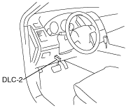
1. Connect the M-MDS (IDS) to the DLC-2.
ac9wzw00000811
|
2. After the vehicle is identified, select the following items from the initialization screen of the IDS.
3. Verify the DTC according to the directions on the screen.
4. After completion of repairs, clear all DTCs stored in the AWD CM. (See Clearing DTCs Procedures.)
Clearing DTCs Procedures
1. Connect the M-MDS (IDS) to the DLC-2.
ac9wzw00000811
|
2. After the vehicle is identified, select the following items from the initialization screen of the IDS.
3. Verify the DTC according to the directions on the screen.
4. Press the clear button on the DTC screen to clear the DTC.
5. Turn the ignition switch to the OFF position.
6. Turn the ignition switch to the ON position and wait for 5 s or more.
7. Perform DTC inspection. (See Reading DTCs Procedure.)
8. Verify that no DTCs are displayed.
DTC Table
|
DTC |
Diagnosis system component |
Page |
|---|---|---|
|
P1887
|
4WD solenoid circuit
|
(See DTC P1887.)
|
|
P1888
|
Differential oil temperature sensor circuit
|
(See DTC P1888.)
|
|
U0073
|
CAN system communication error
|
|
|
U0100
|
Communication error to PCM
|
|
|
U0101
|
Communication error to TCM
|
|
|
U0121
|
Communication error to DSC/RSC HU/CM
|
|
|
U0155
|
Communication error to instrument cluster
|
PID/DATA Monitor Table
|
PID name (definition) |
Unit/Condition |
Operation condition (reference) |
Action |
|---|---|---|---|
|
AAT
|
°C/°F
|
• Ambient air temperature display
|
—
|
|
APP
|
%
|
• Accelerator pedal position display
|
Inspect the accelerator pedal position sensor.
|
|
BOO
|
OFF/ON
|
• Brake pedal released: Off
• Brake pedal depressed: On
|
Inspect the brake switch.
(See BRAKE SWITCH INSPECTION.)
|
|
COUP_SOL
|
%
|
• 4WD solenoid operation condition display
|
Inspect the 4WD solenoid.
(See 4WD SOLENOID INSPECTION.)
|
|
OIL_TEMP
|
°C/°F
|
• Rear differential oil temperature display
|
Inspect the differential oil temperature sensor.
|
|
OIL_TEMP
|
V
|
• Rear differential oil temperature sensor output voltage display
|
Inspect the differential oil temperature sensor.
|
|
VPWR
|
V
|
• Switch the ignition to ON: Approx. 12.2 V
• Idling: Approx. 14.1 V
|
Inspect the 4WD control module.
|
|
WSPD_LF
(Left front ABS wheel-speed sensor input)
|
KPH, MPH
|
• Vehicle stopped: 0 KPH, 0 MPH
• Vehicle running: vehicle speed
|
Inspect the ABS wheel-speed sensor.
|
|
WSPD_LR
(Left rear ABS wheel-speed sensor input)
|
KPH, MPH
|
• Vehicle stopped: 0 KPH, 0 MPH
• Vehicle running: vehicle speed
|
Inspect the ABS wheel-speed sensor.
|
|
WSPD_RF
(Right front ABS wheel-speed sensor input)
|
KPH, MPH
|
• Vehicle stopped: 0 KPH, 0 MPH
• Vehicle running: vehicle speed
|
Inspect the ABS wheel-speed sensor.
|
|
WSPD_RR
(Right rear ABS wheel-speed sensor input)
|
KPH, MPH
|
• Vehicle stopped: 0 KPH, 0 MPH
• Vehicle running: vehicle speed
|
Inspect the ABS wheel-speed sensor.
|
|
4WD_LAMP
|
OFF/BLINK/ON
|
• Control inhibited: ON
• Control paused: BLINK
• Normal: OFF
|
—
|
Active Command Modes Table
|
Command name |
Output part |
Operation |
Operating condition |
|---|---|---|---|
|
4WD_MODE
|
4WD solenoid
|
OFF/ON
|
Ignition switch at ON
|