 |
am6xuw00004814
AUTOMATIC TRANSAXLE REMOVAL/INSTALLATION [AY6A-EL, AY6AX-EL]
id0517k3332000
1. Disconnect the negative battery cable.
2. Remove the battery. (See BATTERY REMOVAL/INSTALLATION [MZI-3.7].)
3. Remove the battery tray. (See BATTERY REMOVAL/INSTALLATION [MZI-3.7].)
4. Remove the fresh-air duct and air cleaner component as a single unit. (See INTAKE-AIR SYSTEM REMOVAL/INSTALLATION [MZI-3.7].)
5. Remove the windshield wiper arm and blade. (See WINDSHIELD WIPER ARM AND BLADE REMOVAL/INSTALLATION.)
6. Remove the cowl grille. (See COWL GRILLE REMOVAL/INSTALLATION.)
7. Remove the cowl panel. (See COWL PANEL REMOVAL/INSTALLATION.)
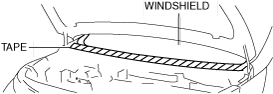
8. Protect the windshield using tape.
am6xuw00004814
|
9. Disconnect the selector cable from the transaxle. (See SELECTOR LEVER COMPONENT REMOVAL/INSTALLATION.)
10. Disconnect the connector and wiring harness from the transaxle.
11. Remove the breather hose component. (See BREATHER COMPONENT REMOVAL/INSTALLATION [AY6A-EL, AY6AX-EL].)
12. Remove the bracket from the transaxle.
am6xuw00004366
|
13. Disconnect the oil hose from the oil pipe component (transaxle side). (See OIL COOLER REMOVAL/INSTALLATION [AY6A-EL, AY6AX-EL].)
14. Disconnect the oil hose from the oil cooler. (See OIL COOLER REMOVAL/INSTALLATION [AY6A-EL, AY6AX-EL].)
15. Disconnect the oil cooler from the transaxle with the water hose connected, and set it out of the way. (See OIL COOLER REMOVAL/INSTALLATION [AY6A-EL, AY6AX-EL].)
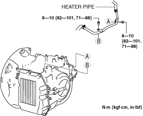
16. Disconnect the heater pipe.
ac9uuw00004033
|
17. Remove the starter. (See STARTER REMOVAL/INSTALLATION [MZI-3.7].)
18. Remove the splash shields. (See SPLASH SHIELD REMOVAL/INSTALLATION.)
19. Remove the side cover.
20. Remove the front wheels and tires. (See GENERAL PROCEDURES (FRONT AND REAR AXLES).)
21. Disconnect the tie-rod end ball joints from the steering knuckles. (See FRONT CROSSMEMBER REMOVAL/INSTALLATION [L.H.D.].) (See FRONT CROSSMEMBER REMOVAL/INSTALLATION [R.H.D.].)
22. Disconnect the front lower arm ball joints from the steering knuckles. (See FRONT LOWER ARM REMOVAL/INSTALLATION.)
23. Disconnect the stabilizer control links from the shock absorbers. (See FRONT STABILIZER REMOVAL/INSTALLATION [L.H.D.].) (See FRONT STABILIZER REMOVAL/INSTALLATION [R.H.D.].)
24. Remove the transverse member. (See TRANSVERSE MEMBER REMOVAL/INSTALLATION.)
25. Disconnect the steering shaft. (See STEERING WHEEL AND COLUMN REMOVAL/INSTALLATION.)
26. Remove the front crossmember bracket. (See FRONT CROSSMEMBER REMOVAL/INSTALLATION [L.H.D.].) (See FRONT CROSSMEMBER REMOVAL/INSTALLATION [R.H.D.].)
27. Remove the No.1 engine mounting bracket bolts. (See ENGINE REMOVAL/INSTALLATION [MZI-3.7].)
28. Remove the No.1 engine mount, No.1 engine mount bracket and the front crossmember as a single unit. (See FRONT CROSSMEMBER REMOVAL/INSTALLATION [L.H.D.].) (See FRONT CROSSMEMBER REMOVAL/INSTALLATION [R.H.D.].)
29. Remove the transfer bracket. (AWD) (See TRANSFER REMOVAL/INSTALLATION.)
30. Drain the ATF. (See AUTOMATIC TRANSAXLE FLUID (ATF) REPLACEMENT [AY6A-EL, AY6AX-EL].)
31. Disconnect the drive shaft (LH) from the transaxle. (See FRONT DRIVE SHAFT REMOVAL/INSTALLATION.)
32. Disconnect the drive shaft (RH) from the joint shaft. (See FRONT DRIVE SHAFT REMOVAL/INSTALLATION.)
33. Remove the joint shaft. (See JOINT SHAFT REMOVAL/INSTALLATION [2WD].)(See JOINT SHAFT REMOVAL/INSTALLATION [4WD].)
34. Remove the transfer. (AWD) (See TRANSFER REMOVAL/INSTALLATION.)
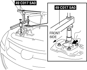
35. Install the SST using the following procedure.
am6xuw00004367
|
ac9uuw00003940
|
ac9uuw00003941
|
ac9uuw00003942
|
36. Remove in the order shown in the figure.
37. Install in the reverse order of removal.
38. Add the ATF. (See AUTOMATIC TRANSAXLE FLUID (ATF) REPLACEMENT [AY6A-EL, AY6AX-EL].)
39. Perform the following test according to the service item. (See MECHANICAL SYSTEM TEST [AY6A-EL, AY6AX-EL].) (See ROAD TEST [AY6A-EL, AY6AX-EL].)
|
Service item |
Test item |
|||
|---|---|---|---|---|
|
Line pressure test |
Stall test |
Time lag test |
Road test |
|
|
Transaxle replacement
|
X
|
|
|
|
|
Transaxle overhaul
|
X
|
X
|
X
|
X
|
|
Torque converter replacement
|
X
|
X
|
|
|
|
Control valve body component replacement
|
X
|
|
|
X
|
am6xuw00004368
|
|
1
|
Torque converter installation nuts
|
|
2
|
No.4 engine mount bracket
|
|
3
|
Transaxle mounting bolt (upper side)
(See Transaxle Removal Note.)
(See Transaxle Installation Note.)
|
|
4
|
Transaxle mounting bolt (lower side)
(See Transaxle Removal Note.)
(See Transaxle Installation Note.)
|
|
5
|
Transaxle
(See Transaxle Removal Note.)
(See Transaxle Installation Note.)
|
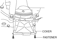
Torque Converter Installation Nuts Removal Note
1. Remove the cover as shown in the figure.
am6xuw00003164
|
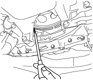
2. Align the holes by turning the torque converter.
3. Insert a flathead screwdriver through the converter housing service hole, and lock the drive plate.
ac9uuw00001656
|
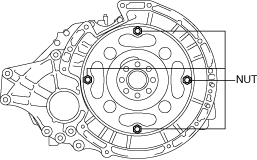
4. Remove the torque converter nuts.
am6xuw00004369
|
Transaxle Removal Note
1. Adjust the SST to tilt the engine to the transaxle side.
ac9uuw00003942
|
2. Support the transaxle on a jack.
ac9uuw00004128
|
3. Remove the transaxle mounting bolts and bracket.
am6xuw00004371
|
4. Remove the transaxle.
Transaxle Installation Note
1. Set the transaxle on a jack and lift it.
ac9uuw00004128
|
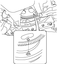
2. Rotate the drive plate so that the logo mark faces upward.
ac9wzw00005628
|
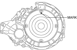
3. Rotate the torque converter so that the mark faces upward.
am6xuw00004372
|
4. Verify that the torque converter stud bolts are inserted into the drive plate bolt holes from the service hole.
ac9uuw00004129
|
5. Install the transaxle mounting bolts and bracket.
am6xuw00004371
|
No.4 Engine Mount Bracket Installation Note
1. Install the No.4 engine mount bracket to the transaxle and temporarily tighten nuts.
ac9uuw00003944
|
2. Temporarily tighten bolt.
3. Temporarily tighten bolt A and nuts B, C.
4. Tighten bolt A, nuts B and C in the order of B→A→C.
5. Tighten bolt D.
Torque Converter Installation Nuts Installation Note
1. Align the holes by turning the torque converter.
2. Insert a screwdriver through the converter housing service hole, and lock the drive plate.
ac9uuw00001657
|
3. Tighten the torque converter mounting nuts.
am6xuw00004369
|
4. Install the cover as shown in the figure.
am6xuw00003164
|