|
1
|
VERIFY ALL SYSTEM DTCs
• Perform the DTC inspection.
• Are any DTCs displayed?
|
Yes
|
Repair the malfunctioning location according to the applicable DTC troubleshooting.
|
|
No
|
Go to the next step.
|
|
2
|
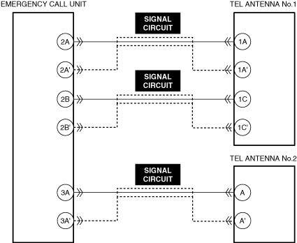
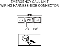
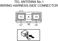
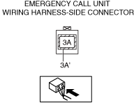
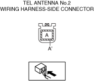
INSPECT EMERGENCY CALL UNIT, TEL ANTENNA NO.1, AND TEL ANTENNA NO.2 CONNECTORS FOR MALFUNCTION
• Inspect the applicable connector and terminal.
• Are the connector and terminal normal?
|
Yes
|
Go to the next step.
|
|
No
|
Repair or replace the malfunctioning location and perform the repair completion verification.
|
|
3
|
INSPECT TEL ANTENNA NO.1 SIGNAL CIRCUIT FOR SHORT TO POWER SUPPLY, SHORT TO GROUND, AND OPEN CIRCUIT
• Inspect the signal circuit for a short to power supply, short to ground, and an open circuit.
• Are the connector and terminal normal?
|
Yes
|
Go to the next step.
|
|
No
|
Repair or replace the malfunctioning location and perform the repair completion verification.
|
|
4
|
INSPECT TEL ANTENNA NO.2 SIGNAL CIRCUIT FOR SHORT TO POWER SUPPLY, SHORT TO GROUND, AND OPEN CIRCUIT
• Inspect the signal circuit for a short to power supply, short to ground, and an open circuit.
• Are the connector and terminal normal?
|
Yes
|
Go to the next step.
|
|
No
|
Repair or replace the malfunctioning location and perform the repair completion verification.
|
|
Repair completion verification1
|
VERIFY THAT VEHICLE IS REPAIRED
• Install/connect the part removed/disconnected during the troubleshooting procedure.
• Has the malfunction symptom been eliminated?
|
Yes
|
Complete the symptom troubleshooting. (Explain contents of repair to customer)
|
|
No
|
Disconnect the TEL antenna No.1 connector and verify the PIDs using the M-MDS.
Emergency call unit
― TEL1_ANT_3LVL
― TEL2_ANT_3LVL
If the PIDs indicates out of range:
• Replace the TEL antenna No.2, then go to the next step.
If the PIDs does not indicate out of range:
• Go to the next step.
|
|
Repair completion verification2
|
VERIFY THAT VEHICLE IS REPAIRED
• Install/connect the part removed/disconnected during the troubleshooting procedure.
• Has the malfunction symptom been eliminated?
|
Yes
|
Complete the symptom troubleshooting. (Explain contents of repair to customer)
|
|
No
|
Replace the TEL antenna No.1, then go to the next step.
|
|
Repair completion verification3
|
VERIFY THAT VEHICLE IS REPAIRED
• Install/connect the part removed/disconnected during the troubleshooting procedure.
• Has the malfunction symptom been eliminated?
|
Yes
|
Complete the symptom troubleshooting. (Explain contents of repair to customer)
|
|
No
|
Refer to the controller area network (CAN) malfunction diagnosis flow to inspect for a CAN communication error.
If the CAN communication is normal, perform the diagnosis from Step 1.
• If the malfunction is not resolved, replace the emergency call unit.
|