LF CONTROL UNIT REMOVAL/INSTALLATION
id091400202100
-
Caution
-
• When replacing the LF control unit, perform the configuration to assure that the system operates correctly.
1. To replace the LF control unit, perform the following procedure.
- (1) Connect the M-MDS to the DLC-2.
-
- (2) Switch the main power ON (READY off).
-
- (3) Activate the M-MDS and perform the following procedure.
-
- 1) Press [Start] to start the vehicle identification.
-
- 2) Press the [Toolbox] tab.
-
- 3) Press the [Work Support] icon.
-
- 4) Press [Configuration].
-
- 5) Press [Run] to perform the configuration.
-
- 6) Press [LFU].
-
- 7) When [Install the new ECU] is displayed, move to the LF control unit replacement procedure.
-
2. Disconnect the negative lead-acid battery terminal. (See NEGATIVE LEAD-ACID BATTERY TERMINAL DISCONNECTION/CONNECTION)
3. Remove the following parts.
- (1) Front scuff plate (RH) (See SCUFF PLATE REMOVAL/INSTALLATION.)
-
- (2) Front side trim (RH) (See FRONT SIDE TRIM REMOVAL/INSTALLATION.)
-
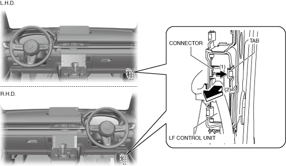
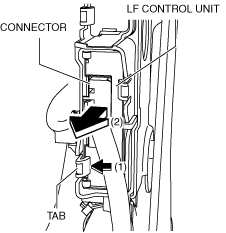
4. While pushing the tab of the bracket in the direction of arrow (1) shown in the figure, pull the connector of the LF control unit in the direction of arrow (2) and pull out the LF control unit from the bracket.
5. While pushing the tab of the bracket in the direction of arrow (1) shown in the figure, pull the connector of the LF control unit in the direction of arrow (2) and pull out the LF control unit from the bracket.
6. Disconnect the connector and remove the LF control unit.
7. Install in the reverse order of removal.
8. If the LF control unit is replaced, perform the following procedure.
- (1) Return to the M-MDS operation and press [Continue].
-
- (2) When the M-MDS processing is completed, press [Next].
-
- (3) When the M-MDS processing is completed, press [Next].
-
- (4) Verify that the following conditions/operations are met/completed, mark the check boxes, and then press [Next].
-
-
• Switch the main power ON (READY off)
• Install battery charger to vehicle
• Lead-acid battery voltage: 11.6 V or more
• Connect power cable to M-MDS
• Front doors on both sides and liftgate are open
- (5) Press [Finish].
-
- (6) Switch the main power OFF.
-
- (7) Switch the main power ON (READY off) to complete the global central configuration (GCC) for the LF control unit.
-
- (8) Perform the immobilizer system-related part programming using the M-MDS. (See IMMOBILIZER SYSTEM-RELATED PARTS PROGRAMMING.)
-
- (9) Clear the DTC. (See CLEARING DTC.)
-