49 L067 006
Plumb bob

49 JP04 001
Target marker

360°VIEW MONITOR SYSTEM AIMING
id152000103600
Special service tool (SST)
|
49 L067 006
Plumb bob
|
|
49 JP04 001
Target marker
|
|
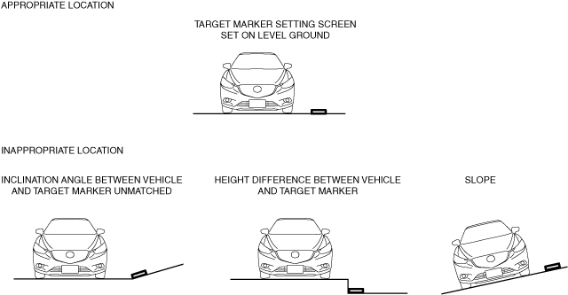
Preparation Before Servicing
1. Empty the vehicle by having all occupants leave the vehicle and remove all the cargo except for the spare tire, jack and tools equipped on the vehicle.
2. Adjust the air pressure of each tire to the specified value.(See WHEEL AND TIRE SPECIFICATION [(E)].)
3. Move the vehicle to level ground.
a30zzw00003812
|
4. Using the M-MDS, perform a DTC inspection of the 360° view monitor control module and verify that no DTCs are displayed. (See DTC INSPECTION.)
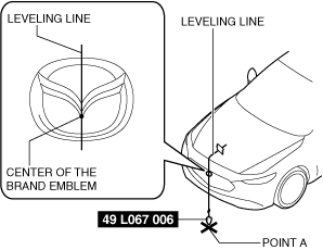
5. Adjust the SST so that it is aligned with the center of the brand emblem, determine the center position at the front of the vehicle, and mark the center position (point A) on the floor surface.
a30zzw00003813
|
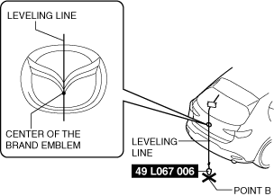
6. Adjust the SST so that it is aligned with the center of the brand emblem, determine the center position at the rear of the vehicle, and mark the center position (point B) on the floor surface.
a30zzw00003814
|
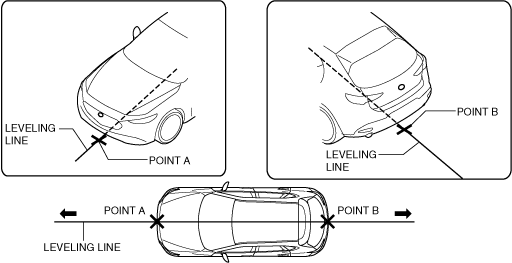
7. Secure the end of the leveling line over point B.
8. Pull the leveling line towards the front and rear of the vehicle and adjust it so that it passes over points A and B.
a30zzw00003815
|
9. Secure the leveling line.
360° View Monitor System Aiming Procedure Selection
|
Step |
Verification and servicing procedure |
Verification and response after servicing |
|
|---|---|---|---|
|
1
|
Was the 360° view monitor control module replaced?
|
Yes
|
Go to Step 4.
|
|
No
|
Go to the next step.
|
||
|
2
|
To determine if aiming is necessary or not, perform the 360° view monitor system screen display verification procedure.
Is Aiming Necessary?
|
Yes
|
Go to the next step.
|
|
No
|
Aiming is completed.
|
||
|
3
|
Which of the cameras requires aiming?
|
Front camera
|
Perform front camera aiming and go to Step 5.
|
|
Side camera
|
Perform side camera aiming and go to Step 5.
(See Side Camera Aiming Procedure.)
|
||
|
Rear mount camera
|
Perform rear mount camera aiming and go to Step 5.
|
||
|
4
|
For the 360° view monitor system aiming (batch aiming), 4 sets of the SST (49 JP04 001) are required.
Are 4 sets of the SST (49 JP04 001) available?
|
Yes
|
Perform 360° view monitor system aiming (batch aiming) and go to Step 5.
|
|
No
|
Individually perform aiming for the camera requiring aiming, then go to Step 5.
(See Side Camera Aiming Procedure.)
|
||
|
5
|
Perform the 360° view monitor system screen display verification procedure.
Is aiming necessary?
|
Yes
|
Perform Step 4 again.
|
|
No
|
Aiming is completed.
|
||
360° View Monitor System Screen Display Verification Procedure
1. Perform the preparation before servicing.
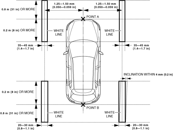
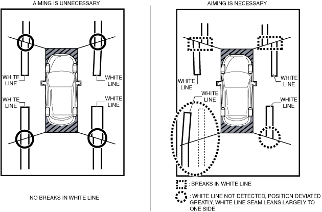
2. Place white lines (paper or tape of 10 mm {0.39 in} or less) at the positions shown in the figure.
All the cameras are verified
a30zzw00003816
|
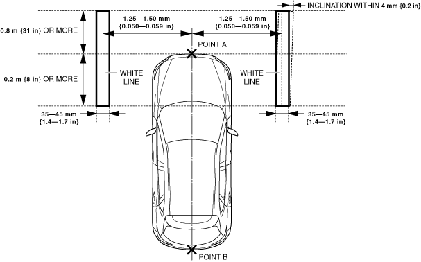
Front camera is verified
a30zzw00003817
|
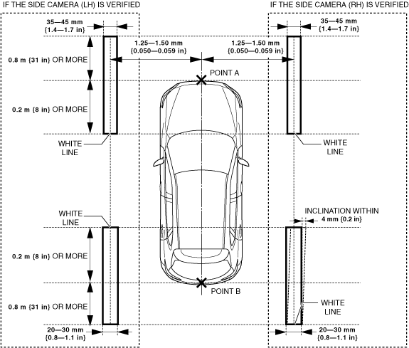
Side camera is verified
a30zzw00003818
|
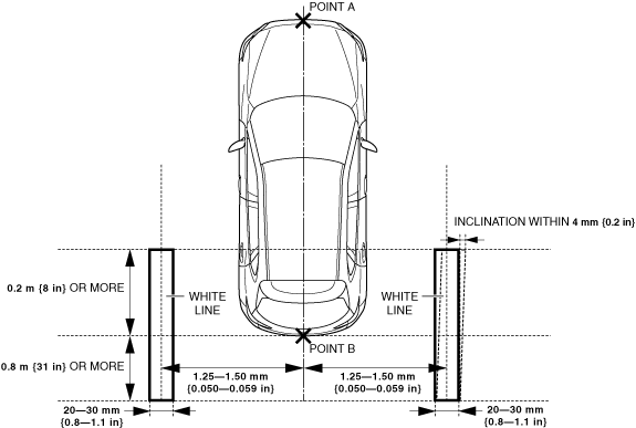
Rear mount camera is verified
a30zzw00003819
|
3. Close all the doors (front door, rear door) and the liftgate.
4. Verify that the outer mirrors are unfolded.
5. Operate the electric parking brake.
6. Shift the selector lever to the P position.
7. Switch the main power ON (READY off or on).
8. Display the screen of the 360° view monitor system on the center display by pressing the 360° view monitor switch.
9. Verify that there are no breaks in the seams of the white lines on the display screen of the center display.
a30zzw00003820
|
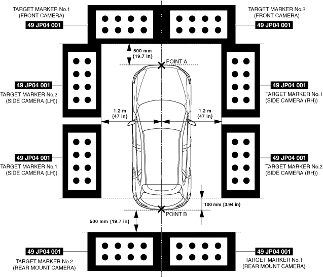
360° View Monitor System Aiming (Batch Aiming) Procedure
1. Position the SSTs at the positions shown in the figure.
a30zzw00003821
|
2. Close all the doors (front door, rear door) and the liftgate.
3. Verify that the outer mirrors are unfolded.
4. Operate the electric parking brake.
5. Shift the selector lever to the P position.
6. Connect the M-MDS to the DLC-2.
7. Switch the main power ON (READY off).
8. Activate the M-MDS and perform the following procedure.
9. Verify the M-MDS display.
|
Error code |
Detection condition |
|---|---|
|
03
|
Target marker No.1 of rear mount camera is not detected
|
|
04
|
Target marker No.2 of rear mount camera is not detected
|
|
06
|
Target marker No.1 of side camera (LH) is not detected
|
|
07
|
Target marker No.2 of side camera (LH) is not detected
|
|
09
|
Target marker No.1 of front camera is not detected
|
|
0A
|
Target marker No.2 of front camera is not detected
|
|
0C
|
Target marker No.1 of side camera (RH) is not detected
|
|
0D
|
Target marker No.2 of side camera (RH) is not detected
|
|
10
|
Input vehicle value exceeds specification
|
|
12
|
Because the following aiming implementation conditions are not met, the aiming is not completed.
• Vehicle stopped
• All doors (front door, rear door) and liftgate closed
• Outer mirrors unfolded
• Electric parking brake operated
• Selector lever is in P position
|
|
15
|
Aiming is not possible due to malfunction in 360° view monitor control module
|
|
16
|
360° view monitor control module cannot receive rear mount camera images
|
|
17
|
360° view monitor control module cannot receive side camera (LH) images
|
|
18
|
360° view monitor control module cannot receive front camera images
|
|
19
|
360° view monitor control module cannot receive side camera (RH) images
|
|
1A
|
Power supply to camera insufficient
|
Error code 03/04/06/07/09/0A/0C/0D/10
|
Step |
Inspection |
Action |
|
|---|---|---|---|
|
1
|
VERIFY TARGET MARKER SETTING ENVIRONMENT AND POSITION
• Verify the following.
• Display the screen of the 360° view monitor system on the center display by pressing the 360° view monitor switch and verify the following.
• Is there a malfunction?
|
Yes
|
Repair the malfunctioning location and go to the next step.
|
|
No
|
Go to the next step.
|
||
|
2
|
PERFORM 360° VIEW MONITOR SYSTEM AIMING
• Perform the 360° view monitor system aiming.
• Was the 360° view monitor system aiming procedure completed correctly?
|
Yes
|
Perform the 360° view monitor system screen display verification procedure.
|
|
No
|
If error code 03/04/06/07/09/0A/0C/0D/10 is displayedIf code other than error code 03/04/06/07/09/0A/0C/0D/10 is displayed
• Go to the next step.
• Go to the procedure for the displayed error code.
|
||
|
3
|
VERIFY DTCs
• Perform the DTC inspection.
(See DTC INSPECTION.)
• Is a DTC displayed?
|
Yes
|
Go to the applicable DTC inspection.
|
|
No
|
If the 360° view monitor system aiming is not completed correctly after performing the 360° view monitor system aiming again, replace the 360° view monitor control module.
|
||
Error code 12/15/16/17/18/19/1A
|
Step |
Inspection |
Action |
|
|---|---|---|---|
|
1
|
PERFORM 360° VIEW MONITOR SYSTEM AIMING
• Perform the 360° view monitor system aiming.
• Was the 360° view monitor system aiming procedure completed correctly?
|
Yes
|
Perform the 360° view monitor system screen display verification procedure.
|
|
No
|
If error code 12/15/16/17/18/19/1A is displayedIf code other than error code 12/15/16/17/18/19/1A is displayed
• Go to the next step.
• Go to the procedure for the displayed error code.
|
||
|
2
|
VERIFY DTCs
• Perform the DTC inspection.
(See DTC INSPECTION)
• Is a DTC displayed?
|
Yes
|
Go to the applicable DTC inspection.
|
|
No
|
If the 360° view monitor system aiming is not completed correctly after performing the 360° view monitor system aiming again, replace the 360° view monitor control module.
|
||
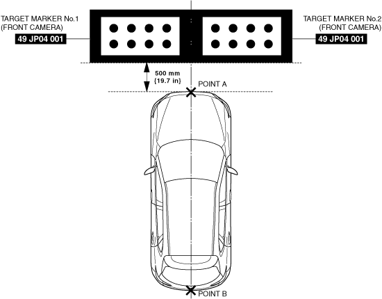
Front Camera Aiming Procedure
1. Position the SSTs at the positions shown in the figure.
a30zzw00003822
|
2. Close all the doors (front door, rear door) and the liftgate.
3. Verify that the outer mirrors are unfolded.
4. Operate the electric parking brake.
5. Shift the selector lever to the P position.
6. Connect the M-MDS to the DLC-2.
7. Switch the main power ON (READY off).
8. Activate the M-MDS and perform the following procedure.
9. Verify the M-MDS display.
|
Error code |
Detection condition |
|---|---|
|
09
|
Target marker No.1 of front camera is not detected
|
|
0A
|
Target marker No.2 of front camera is not detected
|
|
10
|
Input vehicle value exceeds specification
|
|
12
|
Because the following aiming implementation conditions are not met, the aiming is not completed.
• Vehicle stopped
• All doors (front door, rear door) and liftgate closed
• Outer mirrors unfolded
• Electric parking brake operated
• Selector lever is in P position
|
|
15
|
Aiming is not possible due to malfunction in 360° view monitor control module
|
|
18
|
360° view monitor control module cannot receive front camera images
|
|
1A
|
Power supply to camera insufficient
|
Error code 09/0A/10
|
Step |
Inspection |
Action |
|
|---|---|---|---|
|
1
|
VERIFY TARGET MARKER SETTING ENVIRONMENT AND POSITION
• Verify the following.
• Display the screen of the 360° view monitor system on the center display by pressing the 360° view monitor switch and verify the following.
• Is there a malfunction?
|
Yes
|
Repair the malfunctioning location and go to the next step.
|
|
No
|
Go to the next step.
|
||
|
2
|
PERFORM FRONT CAMERA AIMING
• Perform the front camera aiming.
• Was the front camera aiming procedure completed correctly?
|
Yes
|
Perform the 360° view monitor system screen display verification procedure.
|
|
No
|
DTC 09/0A/10 is displayedError code other than error code 09/0A/10 is displayed
• Go to the next step.
• Go to the procedure for the displayed error code.
|
||
|
3
|
VERIFY DTCs
• Perform the DTC inspection.
(See DTC INSPECTION.)
• Is a DTC displayed?
|
Yes
|
Go to the applicable DTC inspection.
|
|
No
|
If the 360° view monitor system aiming is not completed correctly after performing the 360° view monitor system aiming again, replace the 360° view monitor control module.
|
||
Error code 12/15/18/1A
|
Step |
Inspection |
Action |
|
|---|---|---|---|
|
1
|
PERFORM FRONT CAMERA AIMING
• Perform the front camera aiming.
• Was the front camera aiming procedure completed correctly?
|
Yes
|
Perform the 360° view monitor system screen display verification procedure.
|
|
No
|
Error code 12/15/18/1A is displayedError code other than error code 12/15/18/1A is displayed
• Go to the next step.
• Go to the procedure for the displayed error code.
|
||
|
2
|
VERIFY DTCs
• Perform the DTC inspection.
(See DTC INSPECTION.)
• Is a DTC displayed?
|
Yes
|
Go to the applicable DTC inspection.
|
|
No
|
If the 360° view monitor system aiming is not completed correctly after performing the 360° view monitor system aiming again, replace the 360° view monitor control module.
|
||
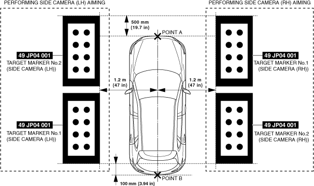
Side Camera Aiming Procedure
1. Position the SSTs at the positions shown in the figure.
a30zzw00003823
|
2. Close all the doors (front door, rear door) and the liftgate.
3. Verify that the outer mirrors are unfolded.
4. Operate the electric parking brake.
5. Shift the selector lever to the P position.
6. Connect the M-MDS to the DLC-2.
7. Switch the main power ON (READY off).
8. Activate the M-MDS and perform the following procedure.
9. Verify the M-MDS display.
|
Error code |
Detection condition |
|---|---|
|
06
|
Target marker No.1 of side camera (LH) is not detected
|
|
07
|
Target marker No.2 of side camera (LH) is not detected
|
|
0C
|
Target marker No.1 of side camera (RH) is not detected
|
|
0D
|
Target marker No.2 of side camera (RH) is not detected
|
|
10
|
Input vehicle value exceeds specification
|
|
12
|
Because the following aiming implementation conditions are not met, the aiming is not completed.
• Vehicle stopped
• All doors (front door, rear door) and liftgate closed
• Outer mirrors unfolded
• Electric parking brake operated
• Selector lever is in P position
|
|
15
|
Aiming is not possible due to malfunction in 360° view monitor control module
|
|
17
|
360° view monitor control module cannot receive side camera (LH) images
|
|
19
|
360° view monitor control module cannot receive side camera (RH) images
|
|
1A
|
Power supply to camera insufficient
|
Error code 06/07/0C/0D/10
|
Step |
Inspection |
Action |
|
|---|---|---|---|
|
1
|
VERIFY TARGET MARKER SETTING ENVIRONMENT AND POSITION
• Verify the following.
• Display the screen of the 360° view monitor system on the center display by pressing the 360° view monitor switch and verify the following.
• Is there a malfunction?
|
Yes
|
Repair the malfunctioning location and go to the next step.
|
|
No
|
Go to the next step.
|
||
|
2
|
PERFORM SIDE CAMERA AIMING
• Perform the side camera aiming.
• Was the side camera aiming procedure completed correctly?
|
Yes
|
Perform the 360° view monitor system screen display verification procedure.
|
|
No
|
If error code 06/07/0C/0D/10 is displayedIf code other than error code 06/07/0C/0D/10 is displayed
• Go to the next step.
• Go to the procedure for the displayed error code.
|
||
|
3
|
VERIFY DTCs
• Perform the DTC inspection.
(See DTC INSPECTION.)
• Is a DTC displayed?
|
Yes
|
Go to the applicable DTC inspection.
|
|
No
|
If the 360° view monitor system aiming is not completed correctly after performing the 360° view monitor system aiming again, replace the 360° view monitor control module.
|
||
Error code 12/15/17/19/1A
|
Step |
Inspection |
Action |
|
|---|---|---|---|
|
1
|
PERFORM SIDE CAMERA AIMING
• Perform the side camera aiming.
• Was the side camera aiming procedure completed correctly?
|
Yes
|
Perform the 360° view monitor system screen display verification procedure.
|
|
No
|
If error code 12/15/17/19/1A is displayedIf code other than error code 12/15/17/19/1A is displayed
• Go to the next step.
• Go to the procedure for the displayed error code.
|
||
|
2
|
VERIFY DTCs
• Perform the DTC inspection.
(See DTC INSPECTION.)
• Is a DTC displayed?
|
Yes
|
Go to the applicable DTC inspection.
|
|
No
|
If the 360° view monitor system aiming is not completed correctly after performing the 360° view monitor system aiming again, replace the 360° view monitor control module.
|
||
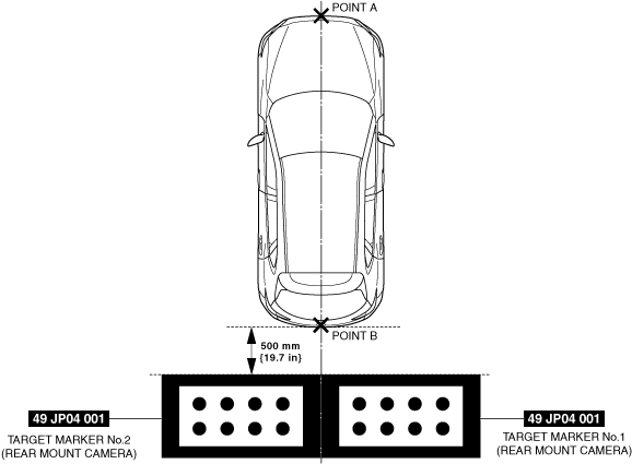
Rear Mount Camera Aiming Procedure
1. Position the SSTs at the positions shown in the figure.
a30zzw00003824
|
2. Close all the doors (front door, rear door) and the liftgate.
3. Verify that the outer mirrors are unfolded.
4. Operate the electric parking brake.
5. Shift the selector lever to the P position.
6. Connect the M-MDS to the DLC-2.
7. Switch the main power ON (READY off).
8. Activate the M-MDS and perform the following procedure.
9. Verify the M-MDS display.
|
Error code |
Detection condition |
|---|---|
|
03
|
Target marker No.1 of rear mount camera is not detected
|
|
04
|
Target marker No.2 of rear mount camera is not detected
|
|
10
|
Input vehicle value exceeds specification
|
|
12
|
Because the following aiming implementation conditions are not met, the aiming is not completed.
• Vehicle stopped
• All doors (front door, rear door) and liftgate closed
• Outer mirrors unfolded
• Electric parking brake operated
• Selector lever is in P position
|
|
15
|
Aiming is not possible due to malfunction in 360° view monitor control module
|
|
16
|
360° view monitor control module cannot receive rear mount camera images
|
|
1A
|
Power supply to camera insufficient
|
Error code 03/04/10
|
Step |
Inspection |
Action |
|
|---|---|---|---|
|
1
|
VERIFY TARGET MARKER SETTING ENVIRONMENT AND POSITION
• Verify the following.
• Display the screen of the 360° view monitor system on the center display by pressing the 360° view monitor switch and verify the following.
• Is there a malfunction?
|
Yes
|
Repair the malfunctioning location and go to the next step.
|
|
No
|
Go to the next step.
|
||
|
2
|
PERFORM REAR MOUNT CAMERA AIMING
• Perform the rear mount camera aiming.
• Was the rear mount camera aiming procedure completed correctly?
|
Yes
|
Perform the 360° view monitor system screen display verification procedure.
|
|
No
|
Error code 03/04/10 is displayedCode other than error code 03/04/10 is displayed
• Go to the next step.
• Go to the procedure for the displayed error code.
|
||
|
3
|
VERIFY DTCs
• Perform the DTC inspection.
(See DTC INSPECTION.)
• Is a DTC displayed?
|
Yes
|
Go to the applicable DTC inspection.
|
|
No
|
If the 360° view monitor system aiming is not completed correctly after performing the 360° view monitor system aiming again, replace the 360° view monitor control module.
|
||
Error code 12/15/16/1A
|
Step |
Inspection |
Action |
|
|---|---|---|---|
|
1
|
PERFORM REAR MOUNT CAMERA AIMING
• Perform the rear mount camera aiming.
• Was the rear mount camera aiming procedure completed correctly?
|
Yes
|
Perform the 360° view monitor system screen display verification procedure.
|
|
No
|
Error code 12/15/16/1A is displayedError code other than error code 12/15/16/1A is displayed
• Go to the next step.
• Go to the procedure for the displayed error code.
|
||
|
2
|
VERIFY DTCs
• Perform the DTC inspection.
(See DTC INSPECTION.)
• Is a DTC displayed?
|
Yes
|
Go to the applicable DTC inspection.
|
|
No
|
If the 360° view monitor system aiming is not completed correctly after performing the 360° view monitor system aiming again, replace the 360° view monitor control module.
|
||