DTC P0A0C:00 [PCM (e-SKYACTIV)]
id300202029900
Outline
System malfunction location |
Interlock switch system: Low input |
||||
---|---|---|---|---|---|
Detection condition
|
• The PCM detects a short to ground in the interlock circuit when the vehicle is stopped.
|
||||
Fail-safe
|
• Refer to "DTC Table" and "Fail-safe Function Malfunction Contents Table". (See DTC TABLE [PCM (e-SKYACTIV)].)
|
||||
Possible cause
|
• Junction box No.3 terminal cover (side) malfunction
• Junction box No.3 terminal cover (upper) malfunction
• Junction box No.3 malfunction
• DC-DC converter internal interlock circuit malfunction
• Electronic A/C compressor internal interlock circuit malfunction
• PTC heater internal interlock circuit malfunction
• Onboard charger internal interlock circuit malfunction
High voltage battery malfunction
• High voltage battery internal interlock circuit malfunction
• Charge port assembly connector or terminal malfunction
• Short to ground in interlock switch circuit
• Interlock switch circuit connector or terminal malfunction
• PCM malfunction
|
||||
![]() |
|||||
![]() |
![]() |
||||
![]() |
|||||
![]() |
![]() |
![]() |
|||
![]() |
|||||
![]() |
![]() |
||||
![]() |
![]() |
![]() |
|||
![]() |
![]() |
||||
![]() |
![]() |
Diagnostic Procedure
Short circuit location determination procedure
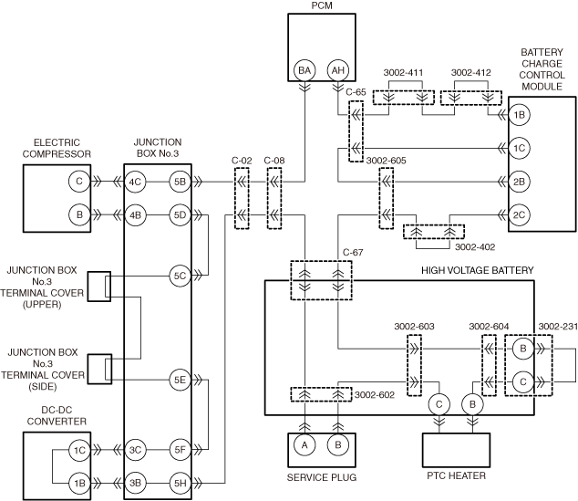
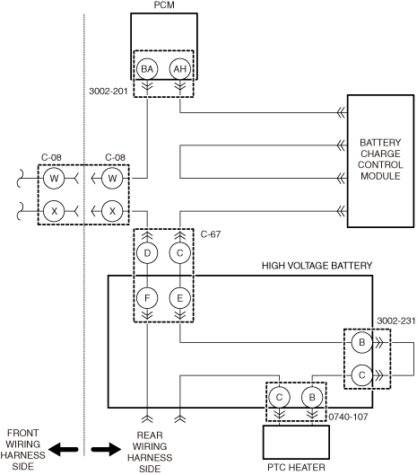
a30zzw00006854
|
Step |
Inspection |
Results |
Action |
---|---|---|---|
1
|
RECORD VEHICLE STATUS WHEN DTC WAS DETECTED TO UTILIZE WITH REPEATABILITY VERIFICATION
• Record the snapshot data.
|
—
|
Go to the next step.
|
2
|
VERIFY WHETHER MALFUNCTION IS PRESENT OR PAST
• Perform the DTC inspection for the PCM.
(See DTC INSPECTION.)
• Is DTC P0A0C:00 a present malfunction?
|
Yes
|
Go to the next step.
|
No
|
Go to the repair completion verification 2.
|
||
3
|
INSPECT CONNECTORS FOR MALFUNCTION
• Disconnect the following connectors and inspect the condition of the connectors and terminals.
(See CONNECTOR INSPECTION.)
• Are the connectors and terminals normal?
|
Yes
|
Go to the next step.
|
No
|
Repair or replace the malfunctioning location and perform the repair completion verification 1.
|
||
4
|
INSPECT CONNECTORS FOR MALFUNCTION
• Remove the service plug.
• After 10 min have elapsed after removing the service plug, perform a zero voltage verification at the voltage detection point of the junction box No.3 to verify that there is no electrical charge in the high voltage circuit.
• Disconnect the following connectors and inspect the condition of the connectors and terminals.
(See CONNECTOR INSPECTION.)
• Are the connectors and terminals normal?
|
Yes
|
Go to the next step.
|
No
|
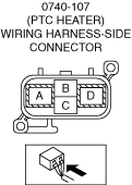
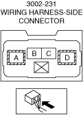
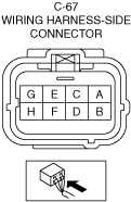
If there are malfunctions with connector 3002-231 (high voltage battery side), connector 0740-107 (high voltage battery side), and connector C-67 (high voltage battery side):
• Replace the high voltage battery, then go to the repair completion verification 1.
If there is a malfunction with connector 3002-231 (high voltage cable side):
• Replace the high voltage cable, then go to the repair completion verification 1.
If there is a malfunction with connector 0740-107 (high voltage cable side):
• Replace the PTC heater, then go to the repair completion verification 1.
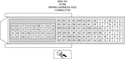
If there are malfunctions with connector C-08 (vehicle wiring harness side), connector C-67 (vehicle wiring harness side), and connector 3002-201 (vehicle wiring harness side):
• Repair or replace the malfunctioning location and perform the repair completion verification 1.
|
||
5
|
DETERMINE SHORT CIRCUIT LOCATION (FRONT WIRING HARNESS SIDE)
• Reinstall the junction box No.3 terminal cover (upper).
• Inspect for continuity between the following terminals and the body ground.
• Is there continuity?
|
Yes
|
Perform the front wiring harness inspection procedure from Step 1.
|
No
|
Go to the next step.
|
||
6
|
DETERMINE SHORT CIRCUIT LOCATION (REAR WIRING HARNESS SIDE)
• Install the jumper wire between the following connector terminals to short them with each other.
• Inspect for continuity between the following terminals and the body ground.
• Is there continuity?
|
Yes
|
Perform the rear wiring harness inspection procedure from Step 1.
|
No
|
Go to the next step.
|
||
7
|
INSPECT HIGH VOLTAGE CABLE INTERLOCK CIRCUIT FOR SHORT TO GROUND
• Inspect for continuity between the following terminals and the body ground.
• Is there continuity?
|
Yes
|
Replace the high voltage cable, then go to the repair completion verification 1.
|
No
|
Go to the next step.
|
||
8
|
INSPECT PTC HEATER INTERLOCK CIRCUIT FOR SHORT TO GROUND
• Inspect for continuity between the following terminals and the body ground.
• Is there continuity?
|
Yes
|
Replace the PTC heater, then go to the repair completion verification 1.
|
No
|
Go to the next step.
|
||
9
|
INSPECT HIGH VOLTAGE BATTERY INTERNAL INTERLOCK CIRCUIT FOR SHORT TO GROUND
• Inspect for continuity between the following terminals and the body ground.
• Is there continuity?
|
Yes
|
Replace the high voltage battery, then go to the repair completion verification 1.
|
No
|
Go to the next step.
|
||
10
|
VERIFY WHETHER MALFUNCTION IS PRESENT OR PAST
• Install/connect the part removed/disconnected during the troubleshooting procedure.
• Clear the DTC recorded in the memory.
(See CLEARING DTC.)
• Replicate the vehicle conditions at the time the DTC was detected using the following procedure.
• Perform the DTC inspection for the PCM.
(See DTC INSPECTION.)
• Is the same Pending DTC present?
|
Yes
|
Refer to the controller area network (CAN) malfunction diagnosis flow to inspect for a CAN communication error.
If the CAN communication is normal, perform the diagnosis from Step 1.
• If the malfunction recurs, replace the PCM, then go to the repair completion verification 1.
(See PCM REMOVAL/INSTALLATION.)
|
No
|
Go to the repair completion verification 2.
|
Front wiring harness inspection procedure
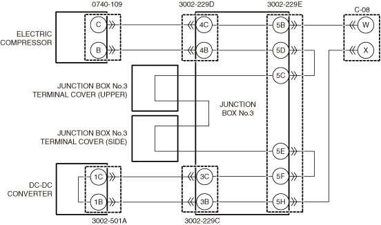
a30zzw00006855
|
Step |
Inspection |
Results |
Action |
---|---|---|---|
1
|
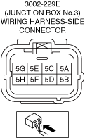
INSPECT CONNECTOR 3002-229E FOR MALFUNCTION
• Disconnect connector 3002-229E.
(See CONNECTOR INSPECTION.)
• Are the connectors and terminals normal?
|
Yes
|
Go to the next step.
|
No
|
Repair or replace the malfunctioning location and perform the repair completion verification 1.
|
||
2
|
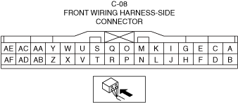
INSPECT FOR SHORT TO GROUND BETWEEN CONNECTOR C-08 AND CONNECTOR 3002-229E
• Inspect for continuity between the following terminals and the body ground.
• Is there continuity?
|
Yes
|
Repair or replace the malfunctioning location and perform the repair completion verification 1.
|
No
|
Go to the next step.
|
||
3
|
INSPECT FOR SHORT TO GROUND BETWEEN CONNECTOR 3002-229E
• Inspect for continuity between the following terminals and the body ground.
• Is there continuity?
|
Yes
|
Repair or replace the malfunctioning location and perform the repair completion verification 1.
|
No
|
Go to the next step.
|
||
4
|
DETERMINE SHORT CIRCUIT LOCATION
• Inspect for continuity between the following terminals and the body ground.
|
—
|
If there is continuity between terminal 5B and GROUND:
• Go to the next step.
If there is continuity between terminal 5C and GROUND:
• Go to step 7.
If there is continuity between terminal 5F and GROUND:
• Go to step 9.
|
5
|
INSPECT FOR SHORT TO GROUND BETWEEN JUNCTION BOX NO.3 AND ELECTRIC COMPRESSOR
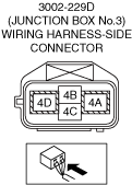
• Disconnect connector 3002-229D.
• Inspect for continuity between the following terminals and the body ground.
• Is there continuity?
|
Yes
|
Go to the next step.
|
No
|
Replace the junction box No.3, then go to the repair completion verification 1.
|
||
6
|
INSPECT ELECTRIC COMPRESSOR INTERNAL INTERLOCK CIRCUIT FOR SHORT TO GROUND
• Disconnect connector 0740-109.
• Install the jumper wire between the following connector terminals to short them with each other
• Inspect for continuity between the following terminals and the body ground.
• Is there continuity?
|
Yes
|
Wear insulating gloves and replace the high voltage cable (electric compressor cable) and perform the repair completion verification 1.
|
No
|
Replace the electric compressor, then go to the repair completion verification 1.
|
||
7
|
INSPECT JUNCTION BOX NO.3 TERMINAL COVER (UPPER) FOR MALFUNCTION
• Remove the junction box No.3 terminal cover (upper).
• Inspect for continuity between the junction box No.3 terminal cover (upper) and the housing.
• Is there continuity?
|
Yes
|
Replace the terminal cover (upper) and perform repair completion verification 1.
|
No
|
Go to the next step.
|
||
8
|
INSPECT JUNCTION BOX NO.3 TERMINAL COVER (SIDE) FOR MALFUNCTION
• Remove the junction box No.3 terminal cover (side).
• Inspect for continuity between the junction box No.3 terminal cover (side) and the housing.
• Is there continuity?
|
Yes
|
Replace the terminal cover (side) and perform repair completion verification 1.
|
No
|
Replace the junction box No.3, then go to the repair completion verification 1.
|
||
9
|
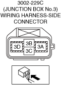
INSPECT FOR SHORT TO GROUND BETWEEN JUNCTION BOX NO.3 AND DC-DC CONVERTER
• Disconnect connector 3002-229C.
• Inspect for continuity between the following terminals and the body ground.
• Is there continuity?
|
Yes
|
Go to the next step.
|
No
|
Replace the junction box No.3, then go to the repair completion verification 1.
|
||
10
|
INSPECT DC-DC-DC CONVERTER INTERNAL INTERLOCK CIRCUIT FOR SHORT TO GROUND
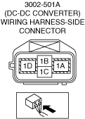
• Disconnect the connector 3002-501A.
• Install the jumper wire between the following connector terminals to short them with each other
• Inspect for continuity between the following terminals and the body ground.
• Is there continuity?
|
Yes
|
Wear insulating gloves and replace the high voltage cable (DC-DC converter cable) and perform the repair completion verification 1.
|
No
|
Replace the DC-DC converter, then go to the repair completion verification 1.
|
Rear wiring harness inspection procedure
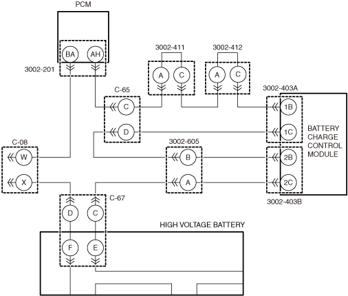
a30zzw00006856
|
Step |
Inspection |
Results |
Action |
---|---|---|---|
1
|
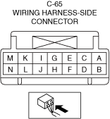
INSPECT FOR SHORT TO GROUND BETWEEN CONNECTOR C-08 AND CONNECTOR 3002-201
• Remove the jumper wire installed to connector 3002-201 (vehicle wiring harness side).
• Inspect for continuity between the following terminals and the body ground.
• Is there continuity?
|
Yes
|
Repair or replace the malfunctioning location and perform the repair completion verification 1.
|
No
|
Go to the next step.
|
||
2
|
INSPECT FOR SHORT TO GROUND BETWEEN CONNECTOR C-65 AND CONNECTOR 3002-201
• Disconnect connector C-65.
• Inspect for continuity between the following terminals and the body ground.
• Is there continuity?
|
Yes
|
Repair or replace the malfunctioning location and perform the repair completion verification 1.
|
No
|
Go to the next step.
|
||
3
|
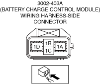
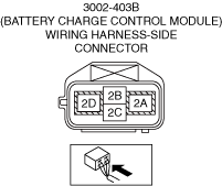
INSPECT FOR SHORT TO GROUND BETWEEN CONNECTOR C-65 AND CONNECTOR 3002-403A
• Inspect for continuity between the following terminals and the body ground.
• Is there continuity?
|
Yes
|
Disconnect connector 3002-403A.
If continuity is lost when connector 3002-403A is removed:
• Go to the next step.
If continuity is present even when connector 3002-403A is removed:
• Repair or replace the malfunctioning location and perform the repair completion verification 1.
|
No
|
Go to step 9.
|
||
4
|
INSPECT ONBOARD CHARGER INTERNAL CIRCUIT FOR SHORT TO GROUND
• Disconnect connector 3002-403A.
• Inspect for continuity between the following terminals and the body ground.
• Is there continuity?
|
Yes
|
Go to the next step.
|
No
|
Replace the onboard charger, then go to the repair completion verification 1.
|
||
5
|
DETERMINE SHORT TO GROUND LOCATION IN WIRING HARNESS BETWEEN CONNECTOR C-65 AND CONNECTOR 3002-403A
• Disconnect connector 3002-412.
• Inspect for continuity between the following terminals and the body ground.
• Is there continuity?
|
Yes
|
Go to step 7.
|
No
|
Go to the next step.
|
||
6
|
INSPECT 3002-412 CONNECTOR INTERNAL CIRCUIT FOR SHORT TO GROUND
• Inspect for continuity between the following terminals and the body ground.
• Is there continuity?
|
Yes
|
Replace the high voltage battery, then go to the repair completion verification 1.
|
No
|
Replace the charge port assembly, then go to the repair completion verification 1.
|
||
7
|
INSPECT FOR SHORT TO GROUND BETWEEN CONNECTOR C-65 AND CONNECTOR 3002-411
• Disconnect connector 3002-411.
• Inspect for continuity between the following terminals and the body ground.
• Is there continuity?
|
Yes
|
Replace the charge port assembly, then go to the repair completion verification 1.
|
No
|
Go to the next step.
|
||
8
|
INSPECT 3002-411 CONNECTOR INTERNAL CIRCUIT FOR SHORT TO GROUND
• Inspect for continuity between the following terminals and the body ground.
• Is there continuity?
|
Yes
|
Replace the high voltage battery, then go to the repair completion verification 1.
|
No
|
Replace the charge port assembly, then go to the repair completion verification 1.
|
||
9
|
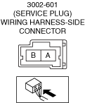
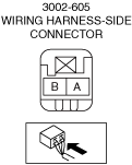
INSPECT FOR SHORT TO GROUND BETWEEN CONNECTOR 3002-605 AND CONNECTOR C-65
• Disconnect connector 3002-605.
• Inspect for continuity between the following terminals and the body ground.
• Is there continuity?
|
Yes
|
Repair or replace the malfunctioning location and perform the repair completion verification 1.
|
No
|
Go to the next step.
|
||
10
|
INSPECT FOR SHORT TO GROUND BETWEEN CONNECTOR 3002-605 AND CONNECTOR 3002-403B
• Inspect for continuity between the following terminals and the body ground.
• Is there continuity?
|
Yes
|
Disconnect connector 3002-403B.
If continuity is lost when connector 3002-403B is removed:
• Go to the next step.
If continuity is present even when connector 3002-403B is removed:
• Repair or replace the malfunctioning location and perform the repair completion verification 1.
|
No
|
Go to step 12.
|
||
11
|
INSPECT FOR SHORT TO GROUND BETWEEN CONNECTOR 3002-605 AND CONNECTOR 3002-403B
• Inspect for continuity between the following terminals and the body ground.
• Is there continuity?
|
Yes
|
Repair or replace the malfunctioning location and perform the repair completion verification 1.
|
No
|
Replace the onboard charger, then go to the repair completion verification 1.
|
||
12
|
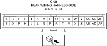
INSPECT FOR SHORT TO GROUND BETWEEN CONNECTOR 3002-605 AND CONNECTOR C-08
• Install the jumper wire between the following connector terminals to short them with each other
• Inspect for continuity between the following terminals and the body ground.
• Is there continuity?
|
Yes
|
If continuity is lost when the jumper wire installed to connector C-67 is removed:
• Replace the wiring harness between connector C-08 and connector C-67.
If continuity is present even when the jumper wire installed to connector C-67 is removed:
• Replace the wiring harness between connector C-67 and connector 3002-605.
|
No
|
Go to the next step.
|
||
13
|
VERIFY IF CAUSE IS SHORT CIRCUIT IN PCM INTERNAL CIRCUIT
• Replace the PCM.
(See PCM REMOVAL/INSTALLATION.)
• Install/connect the part removed/disconnected during the troubleshooting procedure.
• Clear the DTC recorded in the memory.
(See CLEARING DTC.)
• Switch the main power OFF and wait for 30 s or more.
• Switch the main power ON (READY on) and wait for 60 s or more.
• Perform the DTC inspection for the PCM.
(See DTC INSPECTION.)
• Is DTC P0A0C:00 a present malfunction?
|
Yes
|
Replace the high voltage battery, then go to the repair completion verification 1.
|
No
|
Go to the repair completion verification 1.
|
Repair completion verification
Step |
Inspection |
Results |
Action |
---|---|---|---|
Repair completion verification 1
|
VERIFY THAT VEHICLE IS REPAIRED
• Replace the PCM.
(See PCM REMOVAL/INSTALLATION.)
• Install/connect the part removed/disconnected during the troubleshooting procedure.
• Clear the DTC recorded in the memory.
(See CLEARING DTC.)
• Switch the main power OFF and wait for 30 s or more.
• Switch the main power ON (READY on) and wait for 60 s or more.
• Perform the DTC inspection for the PCM.
(See DTC INSPECTION.)
• Is DTC P0A0C:00 a present malfunction?
|
Yes
|
Refer to the controller area network (CAN) malfunction diagnosis flow to inspect for a CAN communication error.
If the CAN communication is normal, perform the diagnosis from Step 1.
• If the malfunction recurs, replace the PCM, then go to the next step.
(See PCM REMOVAL/INSTALLATION.)
|
No
|
Go to the next step.
|
||
Repair completion verification 2
|
VERIFY IF OTHER DTCs DISPLAYED
• Perform the DTC inspection.
(See DTC INSPECTION.)
• Are any other DTCs displayed?
|
Yes
|
Repair the malfunctioning location according to the applicable DTC troubleshooting.
|
No
|
DTC troubleshooting completed.
|