PCM REMOVAL/INSTALLATION
id304000100100
• When replacing the PCM, perform the configuration to assure that the system operates correctly. (See
CONFIGURATION.)
1. When replacing the PCM, perform the configuration using the following procedure.
- (1) Connect the M-MDS to the DLC-2.
-
- (2) Switch the main power ON (READY off).
-
- (3) Activate the M-MDS and perform the following procedure.
-
- 1) Press [Start] to start the vehicle identification.
-
- 2) Press the [Toolbox] tab.
-
- 3) Press the [Work Support] icon.
-
- 4) Press [Configuration].
-
- 5) Press [Run] to perform the configuration.
-
- 6) Press [PCM].
-
- 7) Verify that the main power is switched ON (READY off) and press [Next].
-
-
• If the main power cannot be switched ON (READY off), leave it as it is and press [Next].
- 8) When [Install the new ECU] is displayed, move to the PCM replacement procedure.
-
2. Disconnect the negative lead-acid battery terminal. (See NEGATIVE LEAD-ACID BATTERY TERMINAL DISCONNECTION/CONNECTION.)
3. Remove the following parts:
- (1) Passenger-side scuff plate (See SCUFF PLATE REMOVAL/INSTALLATION.)
-
- (2) Passenger-side front side trim (See FRONT SIDE TRIM REMOVAL/INSTALLATION.)
-
- (3) Passenger-side side wall (See SIDE WALL REMOVAL/INSTALLATION.)
-
- (4) Foot support (See FOOT SUPPORT REMOVAL/INSTALLATION.)
-
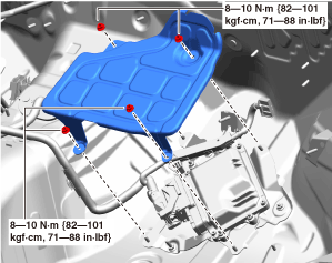
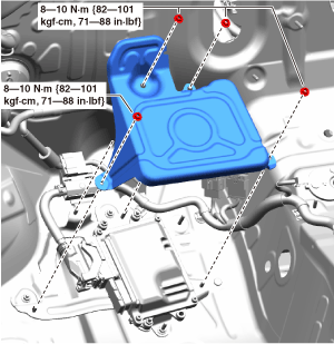
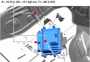
4. Remove the nuts shown in the figure and remove the PCM cover.
L.H.D.
R.H.D.
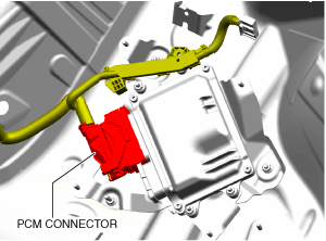
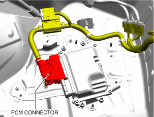
5. Disconnect the PCM connector shown in the figure.
L.H.D.
R.H.D
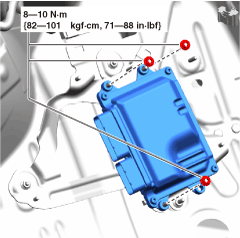
6. Remove the nuts shown in the figure and remove the PCM.
L.H.D.
R.H.D.
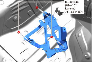
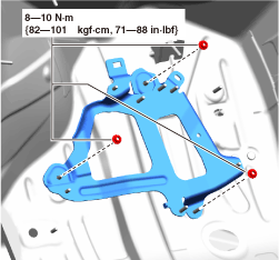
7. Remove the nuts shown in the figure and remove the PCM bracket.
L.H.D.
R.H.D.
8. Install in the reverse order of the removal procedure.
9. If the PCM is replaced, perform the following procedure.
-
Note
-
• Depending on the vehicle conditions, the configuration after PCM replacement may use the data read from the PCM before replacement or the data as of shipment from manufacturer (As-Built data).
• The data used for the configuration is displayed on the lower part of the M-MDS display when the configuration is completed.
- (1) Continue to perform configuration following the instructions on the M-MDS screen.
-
- (2) Perform the immobilizer system-related part programming using the M-MDS. (See IMMOBILIZER SYSTEM-RELATED PARTS PROGRAMMING.)
-
- (3) Perform the DTC inspection. (See DTC INSPECTION.)
-
-
-
― If the DTC is displayed again, repair the malfunctioning location according to the applicable DTC troubleshooting.
PCM Connector Connection Note
1. Connect the PCM connector using the following procedure.
-
Caution
-
• Do not touch the PCM connector terminal. The terminal is extremely thin and can be damaged by touching it.
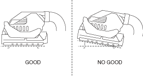
• If the lever is moved with the PCM connector inserted at an angle, the connector itself may be damaged. Verify that the PCM connector is inserted straight.
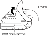
- (1) Press the PCM connector lever until a click sound is heard.
-
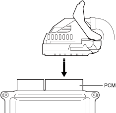
- (2) Align the PCM connector straight to the joint surface.
-
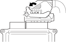
2. Press the PCM connector levers until a click sound is heard.