|
1
|
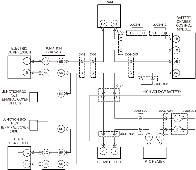
DETERMINE OPEN CIRCUIT LOCATION
-
Warning
-
<<High voltage>>
• Wear insulated gloves when working on a high voltage system.
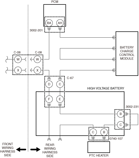
• Verify that jumper wires are installed between the following connector terminals.
-
― Connector C-67 (vehicle wiring harness side)
-
• Terminal D and terminal C
-
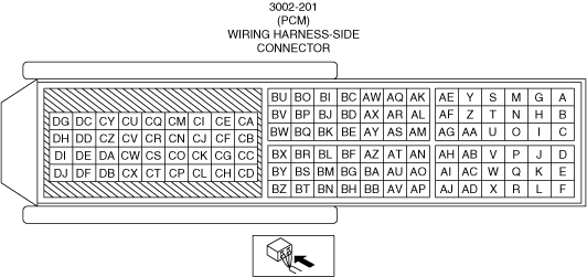
― Connector 3002-201 (vehicle wiring harness side)
-
• Terminal BA and terminal AH
• Install the jumper wire between the following connector terminals to short them with each other.
-
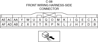
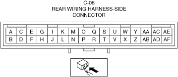
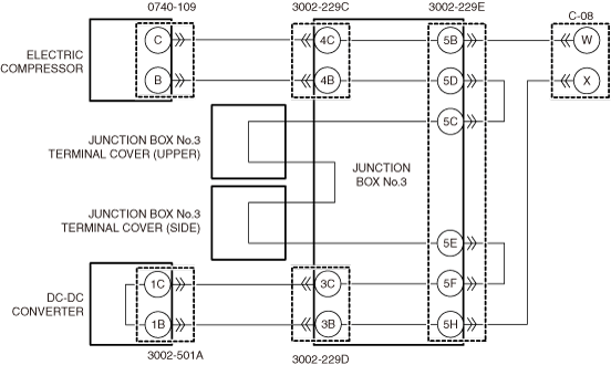
― C-08 (rear wiring harness side)
-
• Terminal W and terminal X
-
Caution
-
• When using the jumper wire, be careful not to short wrong terminals. Otherwise, a vehicle malfunction could occur.
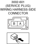
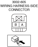
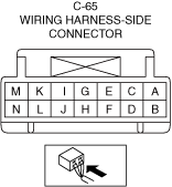
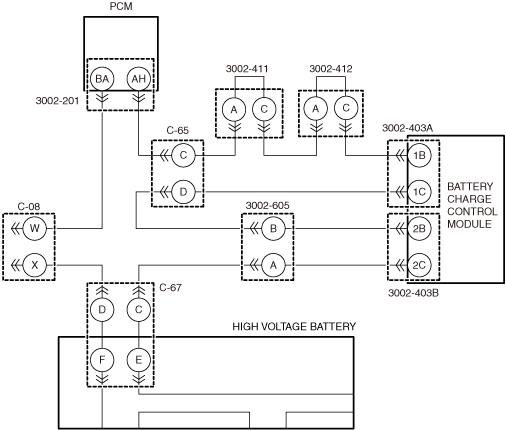
• Disconnect connector C-65 (vehicle wiring harness side) and 3002-605 (vehicle wiring harness side)
• Inspect for continuity between the following terminals of connector.
-
― Connector C-65 (vehicle wiring harness side)
-
• Terminal C
-
― Connector 3002-605 (vehicle wiring harness side
-
• Terminal A
• Is there continuity?
|
Yes
|
Go to step 6.
|
|
No
|
Go to the next step.
|
|
2
|
INSPECT WIRING HARNESS BETWEEN CONNECTOR C-08 AND CONNECTOR 3002-201 FOR OPEN CIRCUIT
• Remove the jumper wire installed to connector 3002-201.
• Inspect for continuity between the following terminals of connector.
-
― C-08 (vehicle wiring harness side)
-
• Terminal W
― 3002-201 (vehicle wiring harness side)
-
• Terminal BA
• Is there continuity?
|
Yes
|
Go to the next step.
|
|
No
|
Repair or replace the malfunctioning location and perform the repair completion verification 1.
|
|
3
|
INSPECT WIRING HARNESS BETWEEN CONNECTOR C-65 AND CONNECTOR 3002-201 FOR OPEN CIRCUIT
• Remove the jumper wire installed to connector 3002-201.
• Inspect for continuity between the following terminals of connector.
-
― C-65 (vehicle wiring harness side)
-
• Terminal C
― 3002-201 (vehicle wiring harness side)
-
• Terminal AH
• Is there continuity?
|
Yes
|
Go to the next step.
|
|
No
|
Repair or replace the malfunctioning location and perform the repair completion verification 1.
|
|
4
|
INSPECT WIRING HARNESS BETWEEN CONNECTOR C-08 AND CONNECTOR C-67 FOR OPEN CIRCUIT
• Remove the jumper wire installed to connector C-08.
• Inspect for continuity between the following terminals of connector.
-
― C-08 (vehicle wiring harness side)
-
• Terminal X
― C-67 (vehicle wiring harness side)
-
• Terminal D
• Is there continuity?
|
Yes
|
Go to the next step.
|
|
No
|
Replace the wiring harness between connector C-08 and connector C-67.
Perform the repair completion verification 1.
|
|
5
|
INSPECT WIRING HARNESS BETWEEN CONNECTOR C-65 AND CONNECTOR 3002-605 FOR OPEN CIRCUIT
• Inspect for continuity between the following terminals of connector.
-
― C-65 (vehicle wiring harness side)
-
• Terminal D
― 3002-605 (vehicle wiring harness side)
-
• Terminal B
• Is there continuity?
|
Yes
|
Replace the wiring harness between connector C-67 and connector 3002-605.
Perform the repair completion verification 1.
|
|
No
|
Repair or replace the malfunctioning location and perform the repair completion verification 1.
|
|
6
|
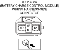
INSPECT WIRING HARNESS BETWEEN CONNECTOR C-65 AND CONNECTOR 3002-403A FOR OPEN CIRCUIT
• Inspect for continuity between the following terminals of connector.
-
― C-65 (charge lid box assembly side)
-
• Terminal C and terminal D
• Is there continuity?
|
Yes
|
Go to step 11.
|
|
No
|
Go to the next step.
|
|
7
|
INSPECT INTERLOCK CIRCUIT IN ONBOARD CHARGER FOR OPEN CIRCUIT
-
Warning
-
<<High voltage>>
• Wear insulated gloves when working on a high voltage system.
• Disconnect connector 3002-403A.
• Install the jumper wire between the following connector terminals to short them with each other.
-
― Connector 3002-403A (vehicle wiring harness side)
-
• Terminal 1B and terminal 1C
-
Caution
-
• When using the jumper wire, be careful not to short wrong terminals. Otherwise, a vehicle malfunction could occur.
• Inspect for continuity between the following terminals of connector.
-
― C-65 (charge lid box assembly side)
-
• Terminal C and terminal D
• Is there continuity?
|
Yes
|
Replace the onboard charger, then go to the repair completion verification 1.
|
|
No
|
Go to the next step.
|
|
8
|
INSPECT WIRING HARNESS BETWEEN CONNECTOR C-65 AND CONNECTOR 3002-403A FOR OPEN CIRCUIT
-
Warning
-
<<High voltage>>
• Wear insulated gloves when working on a high voltage system.
• Remove the jumper wire installed to connector 3002-403A.
• Inspect for continuity between the following terminals of connector.
-
― C-65 (onboard charger side)
-
• Terminal D
-
― Connector 3002-403A (vehicle wiring harness side)
-
• Terminal 1C
• Is there continuity?
|
Yes
|
Go to the next step.
|
|
No
|
Repair or replace the malfunctioning location and perform the repair completion verification 1.
|
|
9
|
INSPECT 3002-411 CONNECTOR INTERNAL CIRCUIT FOR OPEN CIRCUIT
-
Warning
-
<<High voltage>>
• Wear insulated gloves when working on a high voltage system.
• Disconnect connector 3002-411.
• Inspect for continuity between the following terminals of connector.
-
― 3002-411 (high voltage battery side)
-
• Terminal A and terminal C
• Is there continuity?
|
Yes
|
Go to the next step.
|
|
No
|
Replace the high voltage battery, then go to the repair completion verification 1.
|
|
10
|
INSPECT 3002-412 CONNECTOR INTERNAL CIRCUIT FOR OPEN CIRCUIT
-
Warning
-
<<High voltage>>
• Wear insulated gloves when working on a high voltage system.
• Disconnect connector 3002-412.
• Inspect for continuity between the following terminals of connector.
-
― 3002-412 (high voltage battery side)
-
• Terminal A and terminal C
• Is there continuity?
|
Yes
|
Replace the charge port assembly, then go to the repair completion verification 1.
|
|
No
|
Replace the high voltage battery, then go to the repair completion verification 1.
|
|
11
|
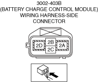
INSPECT WIRING HARNESS BETWEEN CONNECTOR 3002-605 AND CONNECTOR 3002-403B FOR OPEN CIRCUIT
-
Warning
-
<<High voltage>>
• Wear insulated gloves when working on a high voltage system.
• Disconnect connector 3002-605.
• Inspect for continuity between the following terminals of connector.
-
― Connector 3002-605 (charge lid box assembly side)
-
• Terminal A and terminal B
• Is there continuity?
|
Yes
|
Go to step 13.
|
|
No
|
Go to the next step.
|
|
12
|
INSPECT INTERLOCK CIRCUIT IN ONBOARD CHARGER FOR OPEN CIRCUIT
-
Warning
-
<<High voltage>>
• Wear insulated gloves when working on a high voltage system.
• Disconnect connector 3002-403B.
• Install the jumper wire between the following connector terminals to short them with each other.
-
― Connector 3002-403B (vehicle wiring harness side)
-
• Terminal 2B and terminal 2C
-
Caution
-
• When using the jumper wire, be careful not to short wrong terminals. Otherwise, a vehicle malfunction could occur.
• Inspect for continuity between the following terminals of connector.
-
― Connector 3002-605 (charge lid box assembly side)
-
• Terminal A and terminal B
• Is there continuity?
|
Yes
|
Replace the onboard charger, then go to the repair completion verification 1.
|
|
No
|
Repair or replace the malfunctioning location and perform the repair completion verification 1.
|
|
13
|
VERIFY IF CAUSE IS OPEN CIRCUIT IN PCM INTERNAL CIRCUIT
• Install/connect the part removed/disconnected during the troubleshooting procedure.
• Clear the DTC recorded in the memory.
• Switch the main power OFF and wait for 30 s or more.
• Switch the main power ON (READY on) and wait for 60 s or more.
• Perform the DTC inspection for the PCM.
• Is DTC P0A0D:00 a present malfunction?
|
Yes
|
Replace the high voltage battery, then go to the repair completion verification 1.
|
|
No
|
Go to the repair completion verification 2.
|