|
1
|
RECORD VEHICLE STATUS WHEN DTC WAS DETECTED TO UTILIZE WITH REPEATABILITY VERIFICATION
• Record the snapshot data.
-
Note
-
• Recording can be facilitated using the screen capture function of the PC.
|
—
|
Go to the next step.
|
|
2
|
VERIFY DRIVE MOTOR CONTROL MODULE DTCs
• Perform the DTC inspection for the drive motor control module.
• Is DTC P0A78:00 a present malfunction?
|
Yes
|
Repair the malfunctioning location according to the applicable DTC troubleshooting.
|
|
No
|
Go to the next step.
|
|
3
|
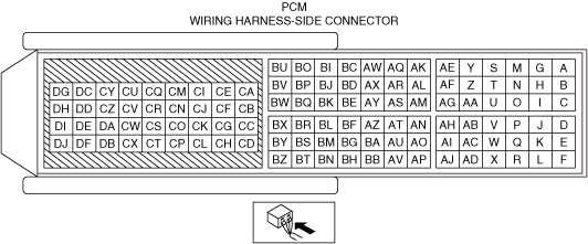
INSPECT PCM CONNECTOR FOR MALFUNCTION
• Inspect the applicable connector and terminal.
• Are the connector and terminal normal?
|
Yes
|
Go to the next step.
|
|
No
|
Repair or replace the malfunctioning location and perform the repair completion verification 1.
|
|
4
|
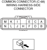
INSPECT COMMON CONNECTOR (C-68) FOR MALFUNCTION
• Inspect the applicable connector and terminal.
• Are the connector and terminal normal?
|
Yes
|
Go to the next step.
|
|
No
|
If there is a malfunction with common connector (C-68) (high voltage battery side):
• Replace the high voltage battery, then go to the repair completion verification 1.
If there is a malfunction with common connector (C-68) (vehicle wiring harness side):
• Repair or replace the malfunctioning location and perform the repair completion verification 1.
|
|
5
|
INSPECT HIGH VOLTAGE CONTACTOR (+) CONTROL CIRCUIT FOR OPEN CIRCUIT
• Inspect the applicable circuit for open circuit.
• Is the circuit normal?
|
Yes
|
Go to the next step.
|
|
No
|
Repair or replace the malfunctioning location and perform the repair completion verification 1.
|
|
6
|
INSPECT HIGH VOLTAGE CONTACTOR (+) CONTROL CIRCUIT FOR SHORT TO GROUND
• Inspect the applicable circuit for short to ground.
• Is the circuit normal?
|
Yes
|
Go to the next step.
|
|
No
|
Repair or replace the malfunctioning location and perform the repair completion verification 1.
|
|
7
|
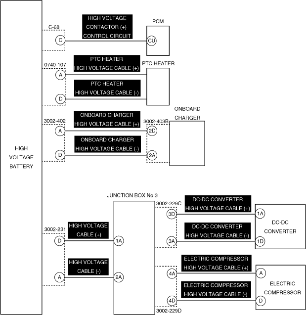
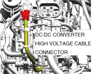
INSPECT DC-DC CONVERTER HIGH VOLTAGE CABLE (+) FOR OPEN CIRCUIT
-
Warning
-
<<High voltage>>
• Wear insulated gloves when working on a high voltage system.
• Remove the service plug.
• After 10 min have elapsed after removing the service plug, perform a zero voltage verification at the voltage detection point of the junction box to verify that there is no electrical charge in the high voltage circuit.
• Disconnect the following high voltage cable connectors.
-
― DC-DC converter high voltage cable connector (DC-DC converter side)
|
Yes
|
Go to the next step.
|
|
No
|
Wear insulating gloves, replace the DC-DC converter high voltage cable, and then perform the repair completion verification.
|
|
8
|
VERIFY IF MALFUNCTION IS CAUSED BY SHORT CIRCUIT IN HIGH VOLTAGE CABLE BETWEEN JUNCTION BOX NO.3 AND DC-DC CONVERTER
-
Warning
-
<<High voltage>>
• Wear insulated gloves when working on a high voltage system.
• Verify that the following connectors are disconnected.
-
― DC-DC converter high voltage cable connector (DC-DC converter side)
-
Warning
-
<<High voltage>>
• For the insulation resistance tester usage, refer to the insulation resistance tester instruction manual. Otherwise, electrocution could result from the voltage generated by the insulation resistance tester.
-
Caution
-
<<High voltage>>
• Use an insulation resistance tester using a testing range of 500 V or less because the voltage applied by the insulation resistance tester may damage the parts.
|
Yes
|
Go to the next step.
|
| |
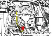
• Wear insulating gloves and measure the resistances between the following terminals using the insulation resistance tester (500 V range).
-
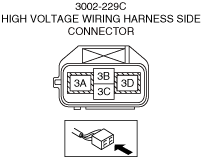
― 3002-229C connector (high voltage wiring harness side)
-
• Between terminal 3A and terminal 3D
• Is the measured value 100 MΩ or more?
|
No
|
Wear insulating gloves, replace the DC-DC converter high voltage cable, and then perform the repair completion verification.
|
|
9
|
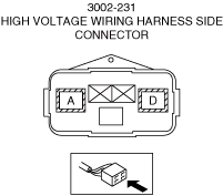
VERIFY IF MALFUNCTION IS CAUSED BY SHORT CIRCUIT IN HIGH VOLTAGE CABLE
-
Warning
-
<<High voltage>>
• Wear insulated gloves when working on a high voltage system.
• Disconnect both ends of the high voltage cable (junction box No.3 side and high voltage battery side).
-
Warning
-
<<High voltage>>
• For the insulation resistance tester usage, refer to the insulation resistance tester instruction manual. Otherwise, electrocution could result from the voltage generated by the insulation resistance tester.
-
Caution
-
<<High voltage>>
• Use an insulation resistance tester using a testing range of 500 V or less because the voltage applied by the insulation resistance tester may damage the parts.
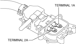
• Wear insulating gloves and measure the resistances between the following terminals using the insulation resistance tester (500 V range).
-
― High voltage cable (junction box No.3 side)
-
• Between terminal 1A and terminal 2A
• Is the measured value 100 MΩ or more?
|
Yes
|
Go to the next step.
|
|
No
|
Replace the high voltage cable, then go to the repair completion verification 1.
|
|
10
|
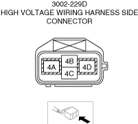
VERIFY IF MALFUNCTION IS CAUSED BY SHORT CIRCUIT IN HIGH VOLTAGE CABLE BETWEEN JUNCTION BOX NO.3 AND ELECTRIC COMPRESSOR
-
Warning
-
<<High voltage>>
• Wear insulated gloves when working on a high voltage system.
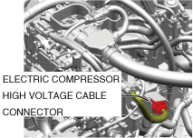
• Disconnect the following high voltage cable connectors.
-
― Electric compressor high voltage cable connector
-
Warning
-
<<High voltage>>
• For the insulation resistance tester usage, refer to the insulation resistance tester instruction manual. Otherwise, electrocution could result from the voltage generated by the insulation resistance tester.
-
Caution
-
<<High voltage>>
• Use an insulation resistance tester using a testing range of 500 V or less because the voltage applied by the insulation resistance tester may damage the parts.
|
Yes
|
Go to the next step.
|
| |
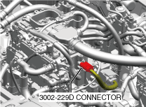
• Wear insulating gloves and measure the resistances between the following terminals using the insulation resistance tester (500 V range).
-
― 3002-229D connector (high voltage wiring harness side)
-
• Between terminal 4A and terminal 4D
• Is the measured value 100 MΩ or more?
|
No
|
Wear insulating gloves, replace the electric compressor high voltage cable, and then perform the repair completion verification.
|
|
11
|
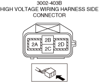
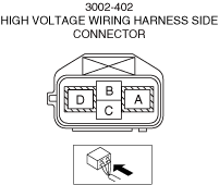
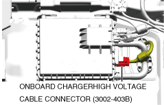
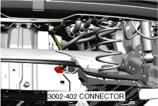
VERIFY IF MALFUNCTION IS CAUSED BY SHORT CIRCUIT IN WIRING HARNESS BETWEEN ONBOARD CHARGER AND CONNECTOR 3002-402
-
Warning
-
<<High voltage>>
• Wear insulated gloves when working on a high voltage system.
• Disconnect the following high voltage cable connectors.
-
― Onboard charger high voltage cable connector (3002-403B)
• Disconnect the following connector.
-
Warning
-
<<High voltage>>
• For the insulation resistance tester usage, refer to the insulation resistance tester instruction manual. Otherwise, electrocution could result from the voltage generated by the insulation resistance tester.
-
Caution
-
<<High voltage>>
• Use an insulation resistance tester using a testing range of 500 V or less because the voltage applied by the insulation resistance tester may damage the parts.
|
Yes
|
Go to the next step.
|
| |
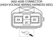
• Wear insulating gloves and measure the resistances between the following terminals using the insulation resistance tester (500 V range).
-
― 3002-403B connector (high voltage wiring harness side)
-
• Between terminal 2A and terminal 2D
• Is the measured value 100 MΩ or more?
|
No
|
Wear insulating gloves, replace the onboard charger high voltage wiring harness, and then perform the repair completion verification.
|
|
12
|
INSPECT JUNCTION BOX No.3 FOR MALFUNCTION
-
Warning
-
<<High voltage>>
• Wear insulated gloves when working on a high voltage system.
• Perform [Insulation Resistance Inspection] for the junction box No.3 inspection.
• Is the insulation resistance within the standard?
|
Yes
|
Go to the next step.
|
|
No
|
Replace the Junction box No.3, then go to repair completion verification 1.
|
|
13
|
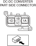
INSPECT DC-DC CONVERTER FOR MALFUNCTION
-
Warning
-
<<High voltage>>
• Wear insulated gloves when working on a high voltage system.
• Install the DC-DC converter high voltage wiring harness connector.
-
Caution
-
• Connect each probe of the circuit tester to the designated terminal. Resistance cannot be accurately measured if reversed.
• Connect the circuit tester probes to the following terminals and measure the resistance between the following terminals.
-
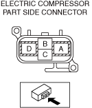
― DC-DC converter part side connector
-
• Terminal 1A: Voltage application side probe
• Terminal 1D: Ground side probe
• Is the resistance 1 MΩ or more?
|
Yes
|
Go to the next step.
|
|
No
|
Replace the DC-DC converter, then go to repair completion verification 1.
|
|
14
|
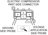
INSPECT ELECTRIC COMPRESSOR FOR MALFUNCTION
-
Warning
-
<<High voltage>>
• Wear insulated gloves when working on a high voltage system.
• Verify that the electric compressor high voltage wiring harness connector is disconnected.
-
Caution
-
• Connect each probe of the circuit tester to the designated terminal. Resistance cannot be accurately measured if reversed.
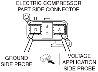
• Connect the circuit tester probes to the following terminals and measure the voltage at the following terminals using diode measurement mode. The measurement is performed 2 times by changing the probe.
-
― Electric compressor part side connector
1st time
-
• Terminal A: Voltage application side probe
• Terminal D: Ground side probe
2nd time
-
• Terminal A: Ground side probe
• Terminal D: Voltage application side probe
• Are the measured values the following values?
-
― 1st measured value: No measured voltage (O.L. display)
― 2nd measured value: 0.39 — 0.73 V
|
Yes
|
Go to the next step.
|
|
No
|
Replace the electric compressor, then go to repair completion verification 1.
|
|
15
|
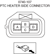
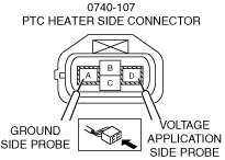
INSPECT PTC HEATER FOR MALFUNCTION
-
Warning
-
<<High voltage>>
• Wear insulated gloves when working on a high voltage system.
• Verify that connector 0740-107 is disconnected.
-
Caution
-
• Connect each probe of the circuit tester to the designated terminal. Resistance cannot be accurately measured if reversed.
• Connect the circuit tester probes to the following terminals and measure the resistance between the following terminals.
-
― Connector 0740-107 (vehicle wiring harness side)
-
• Terminal A: Voltage application side probe
• Terminal D: Ground side probe
• Is the resistance 1 MΩ or more?
|
Yes
|
Go to the next step.
|
|
No
|
Replace the PTC heater, then go to repair completion verification 1.
|
|
16
|
INSPECT ONBOARD CHARGER FOR MALFUNCTION DEPENDING ON REPEATABILITY
-
Warning
-
<<High voltage>>
• Wear insulated gloves when working on a high voltage system.
• Install/connect the part removed/disconnected during the troubleshooting procedure.
• Clear the DTC recorded in the memory.
• Switch the main power OFF and wait for 30 s or more.
• Switch the main power ON (READY on) and wait for 60 s or more.
• Perform the DTC inspection for the PCM.
• Is DTC P0AA2:00 a present malfunction?
|
Yes
|
Replace the onboard charger, then go to the next step.
|
|
No
|
Go to repair completion verification 1.
|
|
17
|
INSPECT PCM FOR MALFUNCTION DEPENDING ON REPEATABILITY
• Install/connect the part removed/disconnected during the troubleshooting procedure.
• Clear the DTC recorded in the memory.
• Switch the main power OFF and wait for 30 s or more.
• Switch the main power ON (READY on) and wait for 60 s or more.
• Perform the DTC inspection for the PCM.
• Is DTC P0AA2:00 a present malfunction?
|
Yes
|
Replace the PCM, then go to the next step.
|
|
No
|
Go to repair completion verification 1.
|
|
18
|
INSPECT HIGH VOLTAGE BATTERY FOR MALFUNCTION DEPENDING ON REPEATABILITY
-
Warning
-
<<High voltage>>
• Wear insulated gloves when working on a high voltage system.
• Install/connect the part removed/disconnected during the troubleshooting procedure.
• Clear the DTC recorded in the memory.
• Switch the main power OFF and wait for 30 s or more.
• Switch the main power ON (READY on) and wait for 60 s or more.
• Perform the DTC inspection for the PCM.
• Is DTC P0AA2:00 a present malfunction?
|
Yes
|
Replace the high voltage battery, then go to the next step.
|
|
No
|
Go to repair completion verification 1.
|
|
Repair completion verification 1
|
VERIFY THAT VEHICLE IS REPAIRED
• Install/connect the part removed/disconnected during the troubleshooting procedure.
• Clear the DTC recorded in the memory.
• Switch the main power OFF and wait for 30 s or more.
• Switch the main power ON (READY on) and wait for 60 s or more.
• Perform the DTC inspection for the PCM.
• Is the same Pending DTC present?
|
Yes
|
Refer to the controller area network (CAN) malfunction diagnosis flow to inspect for a CAN communication error.
If the CAN communication is normal, perform the diagnosis from Step 1.
• If the malfunction recurs, replace the PCM, then go to the next step.
|
|
No
|
Go to the next step.
|
|
Repair completion verification 2
|
VERIFY IF OTHER DTCs DISPLAYED
• Perform the DTC inspection.
• Are any other DTCs displayed?
|
Yes
|
Repair the malfunctioning location according to the applicable DTC troubleshooting.
|
|
No
|
DTC troubleshooting completed
|