|
1
|
RECORD VEHICLE STATUS WHEN DTC WAS DETECTED TO UTILIZE WITH REPEATABILITY VERIFICATION
• Record the snapshot data.
-
Note
-
• Recording can be facilitated using the screen capture function of the PC.
|
—
|
Go to the next step.
|
|
2
|
INSPECT JUNCTION BOX No.3 CONNECTOR FOR MALFUNCTION
-
Warning
-
<<High voltage>>
• Wear insulated gloves when working on a high voltage system.
• Remove the service plug.
• After 10 min have elapsed after removing the service plug, perform a zero voltage verification at the voltage detection point of the junction box No.3 to verify that there is no electrical charge in the high voltage circuit.
• Inspect the applicable connector and terminal.
• Are the connector and terminal normal?
|
Yes
|
Go to the next step.
|
|
No
|
Repair or replace the malfunctioning location and perform the repair completion verification 1.
|
|
3
|
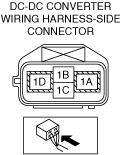
INSPECT DC-DC CONVERTER CONNECTOR FOR MALFUNCTION
-
Warning
-
<<High voltage>>
• Wear insulated gloves when working on a high voltage system.
• Verify that the service plug is removed.
• Inspect the applicable connector and terminal.
• Are the connector and terminal normal?
|
Yes
|
Go to the next step.
|
|
No
|
Repair or replace the malfunctioning location and perform the repair completion verification 1.
|
|
4
|
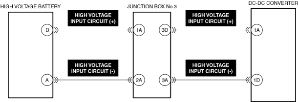
INSPECT DC-DC CONVERTER HIGH VOLTAGE INPUT CIRCUIT (+) FOR OPEN CIRCUIT
-
Warning
-
<<High voltage>>
• Wear insulated gloves when working on a high voltage system.
• Verify that the service plug is removed.
• Refer to the high voltage cable continuity inspection and inspect the continuity between the following terminals.
-
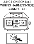
― DC-DC converter side terminal 1A—Junction box No.3 side terminal 3D
• Is the circuit normal?
|
Yes
|
Go to the next step.
|
|
No
|
Repair or replace the malfunctioning location and perform the repair completion verification 1.
|
|
5
|
INSPECT JUNCTION BOX No.3 HIGH VOLTAGE INPUT CIRCUIT (+) FOR OPEN CIRCUIT
-
Warning
-
<<High voltage>>
• Wear insulated gloves when working on a high voltage system.
• Verify that the service plug is removed.
• Refer to the high voltage cable continuity inspection and inspect the continuity between the following terminals.
-
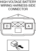
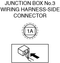
― High voltage battery side terminal D—Junction box No.3 side terminal 1A
• Is the circuit normal?
|
Yes
|
Go to the next step.
|
|
No
|
Repair or replace the malfunctioning location and perform the repair completion verification 1.
|
|
6
|
INSPECT FOR POOR INSULATION BETWEEN HIGH VOLTAGE INPUT CIRCUIT (+) AND HIGH VOLTAGE INPUT CIRCUIT (−) FOR DC-DC CONVERTER
-
Warning
-
<<High voltage>>
• Wear insulated gloves when working on a high voltage system.
• Verify that the service plug is removed.
• Refer to the high voltage cable insulation inspection and inspect the following cable for poor insulation between the high voltage input circuit (+) and high voltage input circuit (−).
-
― High voltage cable (DC-DC converter cable)
• Is the circuit normal?
|
Yes
|
Go to the next step.
|
|
No
|
Repair or replace the malfunctioning location and perform the repair completion verification 1.
|
|
7
|
INSPECT FOR POOR INSULATION BETWEEN HIGH VOLTAGE INPUT CIRCUIT (+) AND HIGH VOLTAGE INPUT CIRCUIT (−) FOR JUNCTION BOX No.3
-
Warning
-
<<High voltage>>
• Wear insulated gloves when working on a high voltage system.
• Verify that the service plug is removed.
• Refer to the high voltage cable insulation inspection and inspect the following cable for poor insulation between the high voltage input circuit (+) and high voltage input circuit (−).
-
• Is the circuit normal?
|
Yes
|
Go to the next step.
|
|
No
|
Repair or replace the malfunctioning location and perform the repair completion verification 1.
|
|
8
|
INSPECT JUNCTION BOX No.3 FOR MALFUNCTION
-
Warning
-
<<High voltage>>
• Wear insulated gloves when working on a high voltage system.
• Inspect the applicable part.
• Is the part normal?
|
Yes
|
Go to the next step.
|
|
No
|
Repair or replace the malfunctioning location and perform the repair completion verification 1.
|
|
9
|
INSPECT HIGH VOLTAGE BATTERY FOR MALFUNCTION DEPENDING ON REPEATABILITY
-
Warning
-
<<High voltage>>
• Wear insulated gloves when working on a high voltage system.
• Install/connect the part removed/disconnected during the troubleshooting procedure.
• Clear the DTC recorded in the memory.
• Replicate the vehicle conditions at the time the DTC was detected using the following procedure.
-
Warning
-
• While performing this step, always operate the vehicle in a safe and lawful manner.
• When the M-MDS is used to observe monitor system status while driving, be sure to have another technician with you, or record the data in the M-MDS using the PID/DATA MONITOR AND RECORD capturing function and inspect later.
-
― Drive the vehicle under the snapshot data condition for 0.1 s or more.
• Perform the DTC inspection for the DC-DC converter.
• Is the same Pending DTC present?
|
Yes
|
Refer to the controller area network (CAN) malfunction diagnosis flow to inspect for a CAN communication error.
• If the CAN communication is normal, replace the high voltage battery, perform the repair completion verification 1.
|
|
No
|
Go to repair completion verification 2.
|
|
Repair completion verification 1
|
VERIFY THAT VEHICLE IS REPAIRED
-
Warning
-
<<High voltage>>
• Wear insulated gloves when working on a high voltage system.
• Install/connect the part removed/disconnected during the troubleshooting procedure.
• Clear the DTC recorded in the memory.
• Replicate the vehicle conditions at the time the DTC was detected using the following procedure.
-
Warning
-
• While performing this step, always operate the vehicle in a safe and lawful manner.
• When the M-MDS is used to observe monitor system status while driving, be sure to have another technician with you, or record the data in the M-MDS using the PID/DATA MONITOR AND RECORD capturing function and inspect later.
-
― Drive the vehicle under the snapshot data condition for 0.1 s or more.
• Perform the DTC inspection for the DC-DC converter.
• Is the same Pending DTC present?
|
Yes
|
Refer to the controller area network (CAN) malfunction diagnosis flow to inspect for a CAN communication error.
If the CAN communication is normal, perform the diagnosis from Step 1.
• If the malfunction recurs, replace the DC-DC converter, then go to the next step.
|
|
No
|
Go to the next step.
|
|
Repair completion verification 2
|
VERIFY IF OTHER DTCs DISPLAYED
• Perform the DTC inspection.
• Are any other DTCs displayed?
|
Yes
|
Repair the malfunctioning location according to the applicable DTC troubleshooting.
|
|
No
|
DTC troubleshooting completed.
|