 |
a30zzw00004495
HIGH VOLTAGE CABLE INSPECTION [(E)]
id3004000007e1
High Voltage Part Inspection And Removal/Installation Notes
Visual Inspection
1. Wear insulating gloves and remove the service plug.
(See SERVICE PLUG REMOVAL/INSTALLATION.)
2. Wear insulating gloves and verify the conditions of the following high voltage wiring harnesses.
3. If the wiring harnesses are damaged or excessively bent, wear insulating gloves and replace the wiring harnesses.
Continuity Inspection
1. Wear insulating gloves and remove the service plug.
(See SERVICE PLUG REMOVAL/INSTALLATION.)
2. Wear insulating gloves and disconnect the terminals (both sides) of the high voltage cable between the high voltage battery and the junction box No.3.
(See HIGH VOLTAGE CABLE REMOVAL/INSTALLATION.)
3. Wear insulating gloves and remove the following high voltage wiring harnesses.
4. Wear insulating gloves and measure the insulation resistances between the following terminals.
High voltage cable resistance values
|
Inspection item |
Terminal to be measured |
Resistance (standard) |
|---|---|---|
|
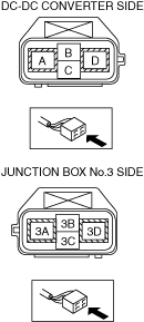
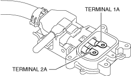
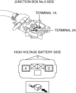
High voltage cable (high voltage battery — junction box No.3)
|
High voltage battery side terminal D — junction box No.3 terminal 1A
|
Less than 1 Ω
|
|
High voltage battery side terminal A — junction box No.3 terminal 2A
|
||
|
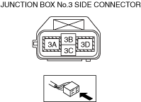
High voltage cable (DC-DC converter cable)
|
DC-DC converter side terminal A — junction box No.3 side terminal 3D
|
|
|
DC-DC converter side terminal D — junction box No.3 side terminal 3A
|
||
|
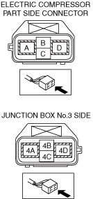
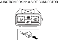
High voltage cable (electric compressor cable)
|
Junction box No.3 side terminal 4A — electric compressor side terminal A
|
|
|
Junction box No.3 side terminal 4D — electric compressor side terminal D
|
||
|
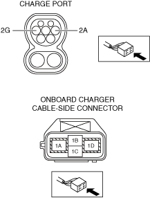
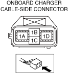
Onboard charger cable
(Charge port — onboard charger)
|
Charge port side terminal 2A — onboard charger side terminal 1A
|
|
|
Charge port side terminal 2G — onboard charger side terminal 1D
|
||
|
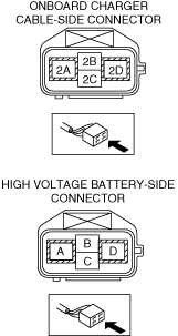
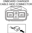
Onboard charger cable
(Onboard charger — high voltage battery)
|
Onboard charger side terminal 2D — high voltage battery side terminal A
|
|
|
Onboard charger side terminal 2A — high voltage battery side terminal D
|
||
|
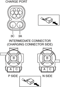
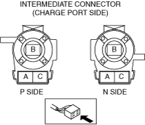
Quick charging cable
(Charge port — intermediate connector)
|
Charge port side terminal 3A — intermediate connector P side terminal B
|
|
|
Charge port side terminal 3C — intermediate connector N side terminal B
|
High voltage cable (high voltage battery — junction box No.3)
a30zzw00004495
|
High voltage cable (DC-DC converter cable)
a30zzw00004739
|
High voltage cable (electric compressor cable)
a30zzw00001972
|
Onboard charger cable (charge port — onboard charger)
a30zzw00006987
|
Onboard charger cable (onboard charger — high voltage battery)
a30zzw00006988
|
Quick charging cable (charge port — intermediate connector)
a30zzw00003963
|
Insulation Inspection
Inspection of insulation against body ground
Insulation inspection of each terminal
1. Wear insulating gloves and remove the service plug.
(See SERVICE PLUG REMOVAL/INSTALLATION.)
2. Wear insulating gloves and disconnect the terminals (both sides) of the high voltage cable between the high voltage battery and the junction box No.3.
(See HIGH VOLTAGE CABLE REMOVAL/INSTALLATION.)
3. Wear insulating gloves and remove the following high voltage wiring harnesses.
4. Wear insulating gloves and insulate the following terminals using electrical tape.
5. Wear insulating gloves and measure the insulation resistances between the following terminals using the insulation resistance tester (500 V range).
High voltage cable insulation resistance values
|
Inspection item |
Terminal to be measured |
Insulation resistance (standard) |
|---|---|---|
|
High voltage cable (high voltage battery — junction box No.3)
|
Terminal 1A — Terminal 2A
|
100 MΩ or more
|
|
High voltage cable (DC-DC converter cable)
|
Terminal 3A — terminal 3D
|
|
|
High voltage cable (electric compressor cable)
|
Terminal 4A — terminal 4D
|
|
|
Onboard charger cable
(Charge port connector — onboard charger)
|
Terminal 1A — terminal 1D
|
|
|
Onboard charger cable
(Onboard charger — high voltage battery)
|
Terminal 2A — terminal 2D
|
|
|
Quick charging cable
(Charge port — intermediate connector)
|
P side terminal B — N side terminal B
|
High voltage cable (high voltage battery — junction box No.3)
a30zzw00004496
|
High voltage cable (DC-DC converter cable)
a30zzw00001976
|
High voltage cable (electric compressor cable)
a30zzw00001977
|
Onboard charger cable (charge port — onboard charger)
a30zzw00006989
|
Onboard charger cable (onboard charger — high voltage battery)
a30zzw00006990
|
Quick charging cable (charge port — intermediate connector)
a30zzw00003965
|