Malfunction symptom
Normal charging does not start
Description
• Charging is not possible even if the normal charge connector is connected to the charge port.
• A charging equipment breaker is tripped and normal charging cannot be started.
• The charge indicator does not flash (green) even if normal charging is started after the charging timer or remote charging is canceled.
Possible cause
Normal charging start conditions are not met:
• EV system malfunction (charging is inhibited by PCM)
-
― PCM related DTCs detected― BECM related DTCs detected― Battery charge control module related DTCs detected
• Main power is not switched OFF
• PCM recognizes that shift lever is in position other than P
-
― Selector lever malfunction― Parking lock actuator malfunction
• High voltage battery is fully charged
• Charging timer is set
• Battery charge control module does not recognize that normal charge connector is connected
-
― Quick charge connector is connected― Poor normal charge connector connection (insufficient insertion, foreign matter caught in connecting area)― CPLT signal circuit malfunction
Charge indicator malfunction:
• Charge indicator malfunction
• Charge indicator illumination circuit malfunction (PCM detects DTC)
AC charge circuit malfunction:
• Poor insulation between AC charge circuit (+) and AC charge circuit (-) of high voltage cable between charge port and onboard charger
• Poor insulation between AC charge circuit (+) and AC charge circuit (-) in onboard charger
Normal charge cable malfunction:
• Malfunction on charging station side
• Onboard charge cable malfunction
-
― Power outlet malfunction (blackout, breaker is actuated)― Outlet plug malfunction― Onboard charge cable malfunction― Poor connection of onboard charge cable
System wiring diagram
• Not applicable
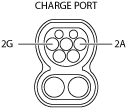
Connector diagram