Step
Inspection
Results
Action
1
VERIFY DTCs
• Inspect for BECM-related DTCs.
(See DTC INSPECTION.)
• DTC P0AA7:00 is output?
Yes
Go to the next step.
No
If any other DTC is output, perform the applicable DTC troubleshooting and repair or replace the malfunctioning location.
2
VERIFY DTCs AGAIN
• Clear the DTC.
(See CLEARING DTC.)
• Switch the main power ON (READY off).
• Inspect for PCM-related DTCs.
(See DTC INSPECTION.)
• Is an electrical leakage-related DTC output?
Yes
Wear insulating gloves and replace the high voltage battery. (Electrical leakage is present at the cells or bus bars in the high voltage battery.)
No
Go to the next step.
3
CUT OFF HIGH VOLTAGE CIRCUIT
-
Warning
-
<<High voltage>>• Wear insulating gloves when working on a high voltage system.
• Remove the service plug.
• After 10 min have elapsed after removing the service plug, wear insulating gloves and perform a zero voltage verification at the voltage detection point of the junction box No.3 to verify that there is no electrical charge in the high voltage circuit.
—
Go to the next step.
4
DETERMINE IF ELECTRICAL LEAKAGE CAUSE IS HIGH VOLTAGE BATTERY OR INVERTER
-
Warning
-
<<High voltage>>• Wear insulating gloves when working on a high voltage system.
• Verify that the service plug is removed.
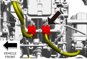
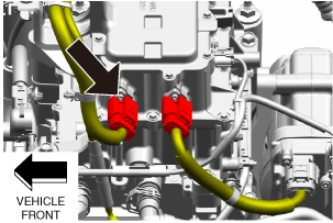
• Wear insulating gloves and disconnect the high voltage cable on the junction box No.3 side.
-
Warning
-
<<High voltage>>• For the insulation resistance tester usage, refer to the insulation resistance tester instruction manual. Otherwise, electrocution could result from the voltage generated by the insulation resistance tester.
-
Caution
-
<<High voltage>>• Use an insulation resistance tester using a testing range of 500 V or less because the high voltage applied by the insulation resistance tester may damage the parts.• The direction of the voltage applied by the insulation resistance tester when measuring the insulation resistance differs depending on the insulation resistance tester manufacturer. To prevent damage to the parts, confirm the voltage application side and ground side probes using the insulation resistance tester instruction manual, and connect the insulation resistance tester probes to the measuring terminals as follows.
-
― Measuring terminal: Voltage application side probe― Body ground side: Ground side probe
During high voltage (+) side circuit measurement:-
― Measuring terminal side: Ground side probe― Body ground side: Voltage application side probe
During high voltage (-) side circuit measurement: -
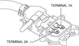
• Wear insulating gloves and measure the insulation resistance between the following terminals using the insulation resistance tester (500 V range).
-
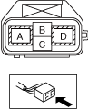
― High voltage cable terminal 1A (Voltage application side probe)—Body ground (Ground side probe)― High voltage cable terminal 2A (Ground side probe)—Body ground (Voltage application side probe)
 a30zzw00004497
High voltage cable terminals:
• Is the insulation resistance more than 100 megohms?
Yes
Go to the next step.
No
Go to Step 9.
5
DETERMINE IF ELECTRICAL LEAKAGE LOCATION IS ON ONBOARD CHARGER SIDE
-
Warning
-
<<High voltage>>• Wear insulating gloves when working on a high voltage system.
• Verify that the service plug is removed.
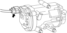
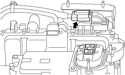
• Wear insulating gloves and disconnect the high voltage system connector of the onboard charger.
a30jjw00000010
|
-
Warning
-
<<High voltage>>• For the insulation resistance tester usage, refer to the insulation resistance tester instruction manual. Otherwise, electrocution could result from the voltage generated by the insulation resistance tester.
-
Caution
-
<<High voltage>>• Use an insulation resistance tester using a testing range of 500 V or less because the high voltage applied by the insulation resistance tester may damage the parts.• The direction of the voltage applied by the insulation resistance tester when measuring the insulation resistance differs depending on the insulation resistance tester manufacturer. To prevent damage to the parts, confirm the voltage application side and ground side probes using the insulation resistance tester instruction manual, and connect the insulation resistance tester probes to the measuring terminals as follows.
-
― Measuring terminal: Voltage application side probe― Body ground side: Ground side probe
During high voltage (+) side circuit measurement:-
― Measuring terminal side: Ground side probe― Body ground side: Voltage application side probe
During high voltage (-) side circuit measurement: -
Yes
Wear insulating gloves and replace the onboard charger. (Electrical leakage is present in the onboard charger.)
No
Go to the next step.
• Wear insulating gloves and measure the insulation resistance between the following terminals using the insulation resistance tester (500 V range).
-
― High voltage cable terminal 1A (Voltage application side probe)—Body ground (Ground side probe)― High voltage cable terminal 2A (Ground side probe)—Body ground (Voltage application side probe)a30zzw00004497
High voltage cable terminals:
• Is the insulation resistance more than 100 megohms?
6
DETERMINE IF ELECTRICAL LEAKAGE LOCATION IS IN HIGH VOLTAGE CABLE (ONBOARD CHARGER CABLE)
-
Warning
-
<<High voltage>>• Wear insulating gloves when working on a high voltage system.
• Verify that the service plug is removed.
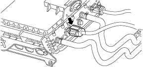
• Wear insulating gloves and disconnect the connector of the onboard charging cable (onboard charger — high voltage battery) shown in the figure.
a30zzw00006986
|
Yes
Wear insulating gloves and replace the onboard charger cable (onboard charger — high voltage battery). (Electrical leakage is present in the onboard charger cable (onboard charger — high voltage battery) )
No
Go to the next step.
-
Warning
-
<<High voltage>>• For the insulation resistance tester usage, refer to the insulation resistance tester instruction manual. Otherwise, electrocution could result from the voltage generated by the insulation resistance tester.
-
Caution
-
<<High voltage>>• Use an insulation resistance tester using a testing range of 500 V or less because the high voltage applied by the insulation resistance tester may damage the parts.• The direction of the voltage applied by the insulation resistance tester when measuring the insulation resistance differs depending on the insulation resistance tester manufacturer. To prevent damage to the parts, confirm the voltage application side and ground side probes using the insulation resistance tester instruction manual, and connect the insulation resistance tester probes to the measuring terminals as follows.
-
― Measuring terminal: Voltage application side probe― Body ground side: Ground side probe
During high voltage (+) side circuit measurement:-
― Measuring terminal side: Ground side probe― Body ground side: Voltage application side probe
During high voltage (-) side circuit measurement: -
• Wear insulating gloves and measure the insulation resistance between the following terminals using the insulation resistance tester (500 V range).
-
― High voltage cable terminal 1A (Voltage application side probe)—Body ground (Ground side probe)― High voltage cable terminal 2A (Ground side probe)—Body ground (Voltage application side probe)a30zzw00004497
High voltage cable terminals:
• Is the insulation resistance more than 100 megohms?
7
DETERMINE IF ELECTRICAL LEAKAGE LOCATION IS ON PTC HEATER SIDE
-
Warning
-
<<High voltage>>• Wear insulating gloves when working on a high voltage system.
• Verify that the service plug is removed.
• Wear insulating gloves and disconnect the high voltage system connector of the PTC heater.
-
Warning
-
<<High voltage>>• For the insulation resistance tester usage, refer to the insulation resistance tester instruction manual. Otherwise, electrocution could result from the voltage generated by the insulation resistance tester.
-
Caution
-
<<High voltage>>• Use an insulation resistance tester using a testing range of 500 V or less because the high voltage applied by the insulation resistance tester may damage the parts.• The direction of the voltage applied by the insulation resistance tester when measuring the insulation resistance differs depending on the insulation resistance tester manufacturer. To prevent damage to the parts, confirm the voltage application side and ground side probes using the insulation resistance tester instruction manual, and connect the insulation resistance tester probes to the measuring terminals as follows.
-
― Measuring terminal: Voltage application side probe― Body ground side: Ground side probe
During high voltage (+) side circuit measurement:-
― Measuring terminal side: Ground side probe― Body ground side: Voltage application side probe
During high voltage (-) side circuit measurement: -
• Wear insulating gloves and measure the insulation resistance between the following terminals using the insulation resistance tester (500 V range).
-
― High voltage cable terminal 1A (Voltage application side probe)—Body ground (Ground side probe)― High voltage cable terminal 2A (Ground side probe)—Body ground (Voltage application side probe)a30zzw00004497
High voltage cable terminals:
• Is the insulation resistance more than 100 megohms?
Yes
Wear insulating gloves and replace the PTC heater. (Electrical leakage is present in the PTC heater.)
No
Go to the next step.
8
DETERMINE IF ELECTRICAL LEAKAGE LOCATION IS IN HIGH VOLTAGE BATTERY OR HIGH VOLTAGE CABLE
-
Warning
-
<<High voltage>>• Wear insulating gloves when working on a high voltage system.
• Verify that the service plug is removed.
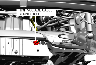
• Wear insulating gloves and disconnect the high voltage cable connector on the high voltage battery side.
a30jjw00000015
|
-
Warning
-
<<High voltage>>• For the insulation resistance tester usage, refer to the insulation resistance tester instruction manual. Otherwise, electrocution could result from the voltage generated by the insulation resistance tester.
-
Caution
-
<<High voltage>>• Use an insulation resistance tester using a testing range of 500 V or less because the high voltage applied by the insulation resistance tester may damage the parts.• The direction of the voltage applied by the insulation resistance tester when measuring the insulation resistance differs depending on the insulation resistance tester manufacturer. To prevent damage to the parts, confirm the voltage application side and ground side probes using the insulation resistance tester instruction manual, and connect the insulation resistance tester probes to the measuring terminals as follows.
-
― Measuring terminal: Voltage application side probe― Body ground side: Ground side probe
During high voltage (+) side circuit measurement:-
― Measuring terminal side: Ground side probe― Body ground side: Voltage application side probe
During high voltage (-) side circuit measurement: -
Yes
Wear insulating gloves and replace the high voltage cable. (Electrical leakage is present in the high voltage cable.)
No
Wear insulating gloves and replace the high voltage battery. (Electrical leakage is present at the cells or bus bars in the high voltage battery.)
• Wear insulating gloves and measure the insulation resistance between the following terminals using the insulation resistance tester (500 V range).
-
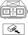
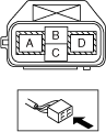
― Cable terminal D (Voltage application side probe)—Body ground (Ground side probe)― Cable terminal A (Ground side probe)—Body ground (Voltage application side probe)
 a30zzw00004740
High voltage battery connector:
• Is the insulation resistance more than 100 megohms?
9
DETERMINE IF ELECTRICAL LEAKAGE LOCATION IS ON ELECTRIC COMPRESSOR SIDE
-
Warning
-
<<High voltage>>• Wear insulating gloves when working on a high voltage system.
• Verify that the service plug is removed.
• Wear insulating gloves and disconnect the high voltage system connector of junction box No.3.
a30zzw00004741
|
-
Warning
-
<<High voltage>>• For the insulation resistance tester usage, refer to the insulation resistance tester instruction manual. Otherwise, electrocution could result from the voltage generated by the insulation resistance tester.
Yes
Go to Step 11.
No
Go to the next step.
-
Caution
-
<<High voltage>>• Use an insulation resistance tester using a testing range of 500 V or less because the high voltage applied by the insulation resistance tester may damage the parts.• The direction of the voltage applied by the insulation resistance tester when measuring the insulation resistance differs depending on the insulation resistance tester manufacturer. To prevent damage to the parts, confirm the voltage application side and ground side probes using the insulation resistance tester instruction manual, and connect the insulation resistance tester probes to the measuring terminals as follows.
-
― Measuring terminal: Voltage application side probe― Body ground side: Ground side probe
During high voltage (+) side circuit measurement:-
― Measuring terminal side: Ground side probe― Body ground side: Voltage application side probe
During high voltage (-) side circuit measurement: -
• Wear insulating gloves and measure the insulation resistance between the following terminals using the insulation resistance tester (500 V range).
-
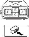
― Cable terminal D (Voltage application side probe)—Body ground (Ground side probe)― Cable terminal A (Ground side probe)—Body ground (Voltage application side probe)
 a30zzw00007151
Cable side connector:
• Is the insulation resistance more than 100 megohms?
10
DETERMINE IF ELECTRICAL LEAKAGE LOCATION IS IN HIGH VOLTAGE CABLE (ELECTRIC COMPRESSOR CABLE)
-
Warning
-
<<High voltage>>• Wear insulating gloves when working on a high voltage system.
• Verify that the service plug is removed.
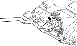
• Wear insulating gloves and disconnect the high voltage system connector of the electric compressor.
a30jjw00000039
|
Yes
Wear insulating gloves and replace the high voltage cable (electric compressor cable). (Electrical leakage is present in the high voltage cable (electric compressor cable).)
No
Wear insulating gloves and replace the electric compressor. (Electrical leakage is present in the electric compressor.)
-
Warning
-
<<High voltage>>• For the insulation resistance tester usage, refer to the insulation resistance tester instruction manual. Otherwise, electrocution could result from the voltage generated by the insulation resistance tester.
-
Caution
-
<<High voltage>>• Use an insulation resistance tester using a testing range of 500 V or less because the high voltage applied by the insulation resistance tester may damage the parts.• The direction of the voltage applied by the insulation resistance tester when measuring the insulation resistance differs depending on the insulation resistance tester manufacturer. To prevent damage to the parts, confirm the voltage application side and ground side probes using the insulation resistance tester instruction manual, and connect the insulation resistance tester probes to the measuring terminals as follows.
-
― Measuring terminal: Voltage application side probe― Body ground side: Ground side probe
During high voltage (+) side circuit measurement:-
― Measuring terminal side: Ground side probe― Body ground side: Voltage application side probe
During high voltage (-) side circuit measurement: -
• Wear insulating gloves and measure the insulation resistance between the following terminals using the insulation resistance tester (500 V range).
-
― Terminal A (Voltage application side probe)—Body ground (Ground side probe)― Terminal D (Ground side probe)—Body ground (Voltage application side probe)
 a30jjw00000041
Electric compressor:
• Is the insulation resistance more than 100 megohms?
11
DETERMINE IF ELECTRICAL LEAKAGE LOCATION IS ON DC-DC CONVERTER SIDE
-
Warning
-
<<High voltage>>• Wear insulating gloves when working on a high voltage system.
• Verify that the service plug is removed.
• Wear insulating gloves and disconnect the high voltage system connector of the junction box No.3.
a30zzw00004743
|
-
Warning
-
<<High voltage>>• For the insulation resistance tester usage, refer to the insulation resistance tester instruction manual. Otherwise, electrocution could result from the voltage generated by the insulation resistance tester.
-
Caution
-
<<High voltage>>• Use an insulation resistance tester using a testing range of 500 V or less because the high voltage applied by the insulation resistance tester may damage the parts.• The direction of the voltage applied by the insulation resistance tester when measuring the insulation resistance differs depending on the insulation resistance tester manufacturer. To prevent damage to the parts, confirm the voltage application side and ground side probes using the insulation resistance tester instruction manual, and connect the insulation resistance tester probes to the measuring terminals as follows.
-
― Measuring terminal: Voltage application side probe― Body ground side: Ground side probe
During high voltage (+) side circuit measurement:-
― Measuring terminal side: Ground side probe― Body ground side: Voltage application side probe
During high voltage (-) side circuit measurement: -
Yes
Go to Step 13.
No
Go to the next step.
• Wear insulating gloves and measure the insulation resistance between the following terminals using the insulation resistance tester (500 V range).
-
― Terminal A (Voltage application side probe)—Body ground (Ground side probe)― Terminal D (Ground side probe)—Body ground (Voltage application side probe)
 a30zzw00007152
Cable side connector:
• Is the insulation resistance more than 100 megohms?
12
DETERMINE IF ELECTRICAL LEAKAGE LOCATION IS IN HIGH VOLTAGE CABLE (DC-DC CONVERTER CABLE)
-
Warning
-
<<High voltage>>• Wear insulating gloves when working on a high voltage system.
• Verify that the service plug is removed.
• Wear insulating gloves and disconnect the high voltage system connector of the DC-DC converter.
a30zzw00001962
|
-
Warning
-
<<High voltage>>• For the insulation resistance tester usage, refer to the insulation resistance tester instruction manual. Otherwise, electrocution could result from the voltage generated by the insulation resistance tester.
Yes
Wear insulating gloves and replace the high voltage cable (DC-DC converter cable). (Electrical leakage is present in the high voltage cable (DC-DC converter cable).)
No
Wear insulating gloves and replace the DC-DC converter. (Electrical leakage is present in the DC-DC converter.)
-
Caution
-
<<High voltage>>• Use an insulation resistance tester using a testing range of 500 V or less because the high voltage applied by the insulation resistance tester may damage the parts.• The direction of the voltage applied by the insulation resistance tester when measuring the insulation resistance differs depending on the insulation resistance tester manufacturer. To prevent damage to the parts, confirm the voltage application side and ground side probes using the insulation resistance tester instruction manual, and connect the insulation resistance tester probes to the measuring terminals as follows.
-
― Measuring terminal: Voltage application side probe― Body ground side: Ground side probe
During high voltage (+) side circuit measurement:-
― Measuring terminal side: Ground side probe― Body ground side: Voltage application side probe
During high voltage (-) side circuit measurement: -
• Wear insulating gloves and measure the insulation resistance between the following terminals using the insulation resistance tester (500 V range).
-
― Terminal A (Voltage application side probe)—Body ground (Ground side probe)― Terminal D (Ground side probe)—Body ground (Voltage application side probe)
 a30jjw00000044
DC-DC converter:
• Is the insulation resistance more than 100 megohms?
13
DETERMINE IF ELECTRICAL LEAKAGE LOCATION IS ON JUNCTION BOX NO.3 SIDE
-
Warning
-
<<High voltage>>• Wear insulating gloves when working on a high voltage system.
• Verify that the service plug is removed.
• Wear insulating gloves and remove the junction box No.3.
-
Warning
-
<<High voltage>>• For the insulation resistance tester usage, refer to the insulation resistance tester instruction manual. Otherwise, electrocution could result from the voltage generated by the insulation resistance tester.
-
Caution
-
<<High voltage>>• Use an insulation resistance tester using a testing range of 500 V or less because the high voltage applied by the insulation resistance tester may damage the parts.
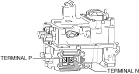
• Wear insulating gloves and measure the insulation resistance between the following terminals and each housing using the insulation resistance tester (500 V range).
-
― Terminal P― Terminal N
 a30zzw00001963
Junction box No.3:
• Is the insulation resistance more than 100 megohms?
Yes
Go to the next step.
No
Wear insulating gloves and replace the junction box No.3. (Electrical leakage is present in the junction box No.3.)
14
DETERMINE IF ELECTRICAL LEAKAGE LOCATION IS IN INVERTER OR ELECTRIC MOTOR
-
Warning
-
<<High voltage>>• Wear insulating gloves when working on a high voltage system.
• Verify that the service plug is removed.
• Wear insulating gloves and remove the inverter.
-
Warning
-
<<High voltage>>• For the insulation resistance tester usage, refer to the insulation resistance tester instruction manual. Otherwise, electrocution could result from the voltage generated by the insulation resistance tester.
-
Caution
-
<<High voltage>>• Use an insulation resistance tester using a testing range of 500 V or less because the high voltage applied by the insulation resistance tester may damage the parts.
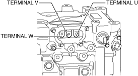
• Wear insulating gloves and measure the insulation resistance between the following terminals and each housing using the insulation resistance tester (500 V range).
-
― Terminal U― Terminal V― Terminal W
 a30zzw00001966
Electric motor:
• Is the insulation resistance more than 100 megohms?
Yes
Wear insulating gloves and replace the inverter. (Electrical leakage is present in the inverter.)
No
Wear insulating gloves and replace the electric motor. (Electrical leakage is present in the electric motor.)