INVERTER REMOVAL/INSTALLATION
id301000100400
Replacement parts
|
Gasket
Quantity: 1
Location of use: Electric motor
|
Gasket
Quantity: 1
Location of use: Inverter
|
|
Clip
Quantity: 3
Location of use: Location of use: Insulator
|
Quick release connector
Quantity: 1
Location of use: Water pipe and water hose connection
|
-
Warning
-
<<High voltage>>
• If the necessary measures are not taken before servicing an electric vehicle, it could cause electrical shock and result in serious injury or, in the worst case, death. Before servicing the electric vehicle, refer to [HIGH VOLTAGE SERVICE CAUTIONS] in the general information and implement the necessary measures. (See
HIGH VOLTAGE SERVICE CAUTIONS.)
High Voltage Part Inspection And Removal/Installation Notes
-
Warning
-
<<High voltage>>
• If necessary measures such as wearing the correct protective gear are not taken when inspecting or removing/installing the high voltage parts, it could cause electrical shock and result in serious injury or, in the worst case, death.
• Before inspecting or removing/installing the high voltage parts, refer to [HIGH VOLTAGE SERVICE CAUTIONS] in the general information and [High Voltage Part Inspection and Removal/Installation Notes] of the high voltage system service cautions and implement the necessary measures and preparations. (See
HIGH VOLTAGE SERVICE CAUTIONS.) (See
HIGH VOLTAGE SYSTEM SERVICE CAUTIONS.)
-
Warning
-
• The EV system is hot immediately after driving and charging, and can cause severe burns. Turn off the EV system and wait until it is cool before performing the servicing.
• If the cooling system cap is removed while the EV system is hot, hot coolant may be ejected, causing severe burns or injury. Perform the removal of the cooling system cap when the EV system is cool.
• When removing the cooling system cap, cover the cooling system cap with a clean cloth and remove it slowly.
• The cooling fan may suddenly start operating regardless of the main power switch position. Keep hands and tools away from the cooling fan even if the cooling fan is not operating to prevent injury, or damage to the cooling fan. When servicing the cooling fan or parts near the cooling fan, ensure the following.
-
― Do not perform normal charging or quick charging
― Do not select high voltage battery cooling on center display after EV system stops
― Do not open/close doors frequently with main power switched OFF
― Access connected vehicle maintenance mode (MyMazda App connected vehicle)
― Cancel climate control timer
― Operate center display and turn off battery heater operation
1. Place the vehicle onto an auto lift and prepare it so it can be lifted up.
2. Verify that the READY indicator on the instrument cluster is not illuminated.
-
• If the READY indicator is turned on, switch the main power OFF.
3. Disconnect the negative lead-acid battery terminal. (See NEGATIVE LEAD-ACID BATTERY TERMINAL DISCONNECTION/CONNECTION.)
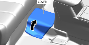
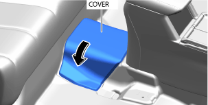
4. Partially peel back the cover.
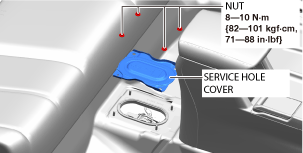
5. Remove the service hole cover.
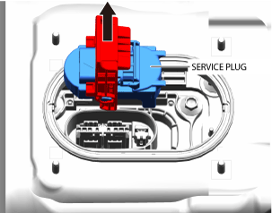
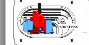
6. Wear insulating gloves and remove the service plug using the following procedure.
-
Warning
-
<<High voltage>>
• Touching the terminal on the vehicle side can result in serious injury or death from electric shock. For this reason, after removing the service plug, cover the vehicle-side terminals with insulating tape so that they cannot be touched.
• Do not touch high voltage parts for 10 min after removing service plug. Electric charges may be stored on the condenser for 10 min after the service plug is removed, and touching high voltage parts during that time can result in serious injury or death from electric shock.
• Service plugs must be removed by workers inspecting/removing/installing high voltage parts. Keep the removed service plug on your person until inspection/removal/installation of the high voltage parts is completed to prevent other workers from accidentally installing the service plug.
-
Caution
-
<<High voltage>>
• After removing the service plug, cover the vehicle side terminals with insulating tape to prevent foreign matter from adhering to them.
• When you are keeping the service plug on your person, cover the service plug terminals with insulating tape to prevent damage to them.
• Do not switch the main power ON (READY on) after removing the service plug. If the main power is switched ON (READY on) after removing the service plug, the vehicle may malfunction.
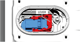
- (1) Slide the lock in the direction of the arrow shown in the figure. (Do not pull out completely)
-
- (2) Raise the lever.
-
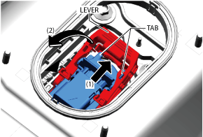
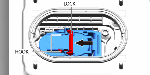
- (3) Press the area indicated by arrow (1) shown in the figure, release the tabs, and then raise the lever until it is perpendicular.
-
- (4) Hold the lever and pull the service plug straight up.
-
7. After removing the service plug, leave it for 10 min.
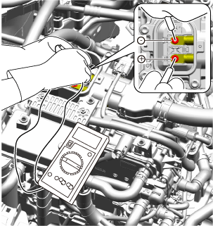
8. Wear insulating gloves and measure the voltage at the high voltage cable connection (junction box No.3 side) using the following procedure.
- (1) Remove the seal cover. (See SEAL COVER REMOVAL/INSTALLATION.)
-
-
Caution
-
<<High voltage>>
• Be careful not to allow foreign matter or water droplets to enter the junction box No.3. Since the junction box No.3 has a high voltage circuit, there is a risk of malfunction if foreign matter or water drops enter it.
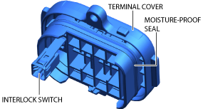
• Remove the terminal cover by pulling it straight up. The terminal cover is fitted with an interlock switch. This interlock switch may be damaged if the terminal cover is removed while being tilted.
• Do not touch the moisture-proof seal on the terminal cover. If the seal is touched or damaged, replace the terminal cover.
- (2) Remove the terminal cover.
-
- (3) Measure the voltage at the high voltage cable connection.
-
-
Note
-
• Use a voltmeter with a measurement range of
450 V DC or more.
-
― Verify that the voltmeter indicates 0 V and go to the next step.
9. Remove front under cover No.2. (See FRONT UNDER COVER No.2 REMOVAL/INSTALLATION.)
10. Implement [Coolant Draining Procedure] for the coolant replacement. (See COOLANT REPLACEMENT.)
11. Remove the coolant reserve tank. (See COOLANT RESERVE TANK REMOVAL/INSTALLATION.)
12. Remove the DC-DC converter. (See DC-DC CONVERTER REMOVAL/INSTALLATION.)
13. Disconnect the high voltage cable (junction box No.3 side). (See HIGH VOLTAGE CABLE REMOVAL/INSTALLATION.)
-
• After disconnecting the high voltage cable, wrap the terminal part with insulating tape to insulate it.
14. Remove the junction box No.3. (See JUNCTION BOX No.3 REMOVAL/INSTALLATION.)
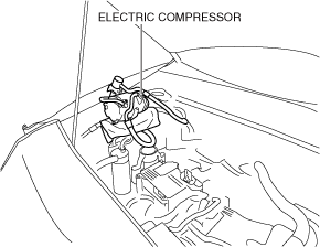
15. Remove the A/C compressor with the A/C hoses and the pipes connected, and secure it using wire or rope so that it does not interfere with the work. (See ELECTRIC COMPRESSOR REMOVAL/INSTALLATION.)
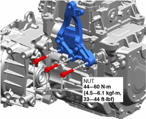
16. Remove the A/C compressor bracket. (See ELECTRIC COMPRESSOR REMOVAL/INSTALLATION.)
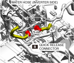
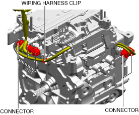
17. Disconnect the water hoses shown in the figure. (Disconnect from the inverter side.) (See Quick Release Connector Removal)(See Quick Release Connector Installation)
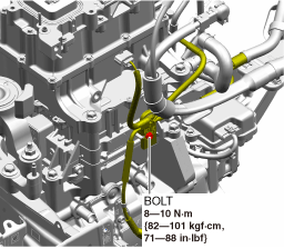
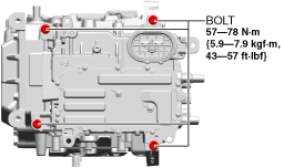
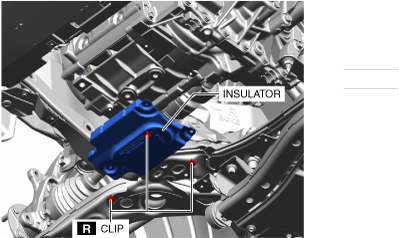
18. Remove the bolt shown in the figure and remove the wiring harness.
19. Remove the bolt shown in the figure and remove the bracket.
20. Disconnect the connectors and wiring harness clip shown in the figure.
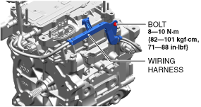
21. Remove the bolt shown in the figure and remove the wiring harness.
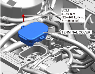
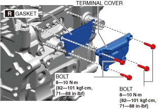
22. Wear insulating gloves and remove the bolts shown in the figure, then remove the terminal cover.
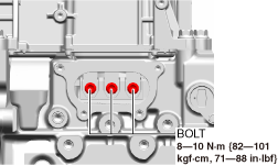
23. Wear insulating gloves and remove the bolts shown in the figure, then disconnect the bus bar.
24. Wear insulating gloves and remove the bolts shown in the figure.
25. Wear insulating gloves, pull the inverter straight up, and then remove it.
-
Caution
-
• After removing the inverter, place it on a wood slab so as not to damage the bus bars.
-
• After removing the inverter, wear insulating gloves and wrap the exposed terminal part with insulating tape to insulate it.
26. Install in the reverse order of removal.
-
Caution
-
• Before connecting the service plug, check the tightness of the high voltage terminals and the connection status of the connectors.
27. Wear insulating gloves and install the service plug using the following procedure.
- (1) Insert the service plug as far as it will go.
-
- (2) Depress the lever completely.
-
- (3) Slide the lock in the direction of the arrow shown in the figure until the hook is engaged.
-
28. Install the service hole cover.
29. Close the cover.
30. Connect the negative lead-acid battery terminal. (See NEGATIVE LEAD-ACID BATTERY TERMINAL DISCONNECTION/CONNECTION.)
31. Implement [Coolant Replenishment Procedure] for the coolant replacement. (See COOLANT REPLACEMENT.)
32. Implement [Air Bleeding Procedure] for the coolant replacement. (See COOLANT REPLACEMENT.)
33. Inspect to confirm that there is no coolant leakage at any part. (See COOLANT LEAKAGE INSPECTION.)
34. Install the insulator.
35. Install front under cover No.2. (See FRONT UNDER COVER No.2 REMOVAL/INSTALLATION.)
36. Lower the vehicle to the ground and adjust the coolant amount to the F line on the coolant reserve tank.
37. Install the seal cover. (See SEAL COVER REMOVAL/INSTALLATION.)
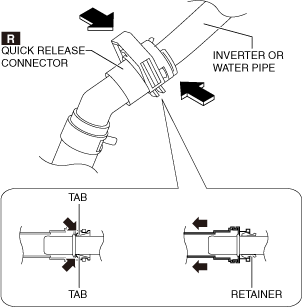
Quick Release Connector Removal
1. Remove the quick release connector using the following procedure.
- (1) Press the tab on the retainer to detach the quick release connector.
-
-
Note
-
• The retainer remains attached to the inverter or water pipe even if the quick release connector is disconnected.
- (2) While holding down the retainer tab, pull on the quick release connector and disconnect it.
-
- (3) Protect the disconnected quick release connector, inverter, and water pipe by wrapping them in plastic to prevent damage or soiling.
-
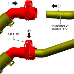
Quick Release Connector Installation
1. Inspect the sealing surface of the inverter and water pipe for damage or deformation.
-
• If there is any malfunction, perform replacement.
2. Install the quick release connector in the order shown in the figure.
3. Install the quick release connector in the order shown in the figure.