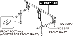
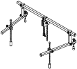
49 C017 5A0
Engine support set
ELECTRIC MOTOR REMOVAL/INSTALLATION
id301000100600
Special service tool (SST)
|
49 C017 5A0
Engine support set
|
|
High Voltage Part Inspection And Removal/Installation Notes
Motor Removal Preparation
1. Place the vehicle onto an auto lift and prepare it so it can be lifted up.
2. Verify that the READY indicator on the instrument cluster is not illuminated.
3. Disconnect the negative lead-acid battery terminal. (See NEGATIVE LEAD-ACID BATTERY TERMINAL DISCONNECTION/CONNECTION.)
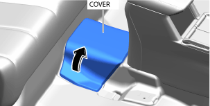
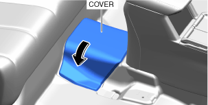
4. Partially peel back the cover.
a30zzw00004019
|
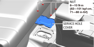
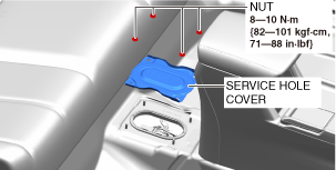
5. Remove the service hole cover.
a30zzw00004020
|
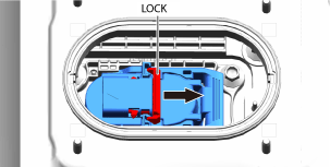
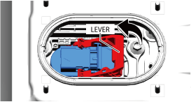
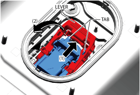
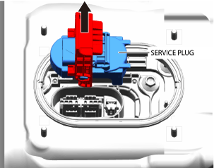
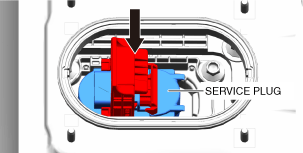
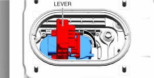
6. Wear insulating gloves and remove the service plug using the following procedure.
a30zzw00004021
|
a30zzw00004502
|
a30zzw00004503
|
a30zzw00004023
|
7. After removing the service plug, leave it for 10 min.
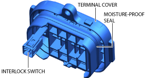
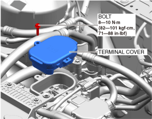
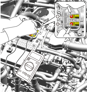
8. Wear insulating gloves and measure the voltage at the high voltage cable connection (junction box No.3 side) using the following procedure.
a30zzw00004024
|
a30zzw00006972
|
a30zzw00004025
|
Coolant draining procedure
Replacement part
|
Clip
Quantity: 3
Location of use: Insulator
|
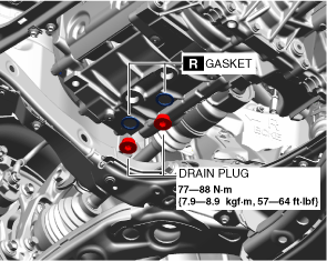
Gasket
Quantity: 2
Location of use: Drain plug
|
1. Remove the cooling system cap.
2. Remove front under cover No.2. (See FRONT UNDER COVER No.2 REMOVAL/INSTALLATION.)
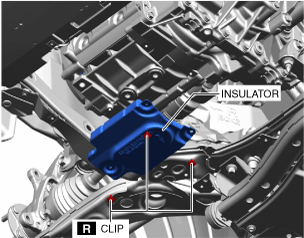
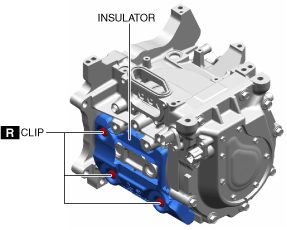
3. Remove the clips and remove the insulator shown in the figure.
a30zzw00007284
|
4. Remove the drain plugs shown in the figure and drain the coolant.
a30zzw00007285
|
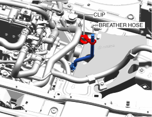
5. Remove the breather hose clip of the transaxle from the water hose and set the breather hose aside.
a30zzw00007286
|
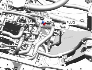
6. Place a clean cloth around the plug shown in the figure so that coolant does not flow out onto places such as the motor case.
a30zzw00007287
|
7. Remove the plug.
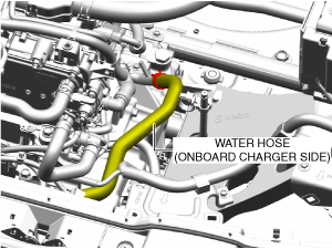
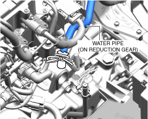
8. Remove the water hose (onboard charger side) shown in the figure from the water pipe (on deceleration mechanism).
a30zzw00007288
|
9. Install the plug.
10. Install the drain plugs.
Motor Removal
Replacement part
|
Clip
Quantity: 8
Location of use: Insulator
|
O-ring
Quantity: 1
Location of use: Rotor shaft
|
1. Remove the joint cover. (See INTERMEDIATE SHAFT REMOVAL/INSTALLATION.)
2. Disconnect the Intermediate shaft (lower side) from the steering gear and linkage. (See INTERMEDIATE SHAFT REMOVAL/INSTALLATION.)
3. Drain the ATF. (See AUTOMATIC TRANSAXLE FLUID (ATF) REPLACEMENT [A71M].)
4. Remove the wheel and tire. (See WHEEL AND TIRE REMOVAL/INSTALLATION.)
5. Remove front under cover No.1. (See FRONT UNDER COVER No.1 REMOVAL/INSTALLATION.)
6. Remove the gusset. (See FRONT CROSSMEMBER REMOVAL/INSTALLATION.)
7. Remove floor under cover No.1. (See FLOOR UNDER COVER REMOVAL/INSTALLATION.)
8. Remove the guard component. (See GUARD COMPONENT REMOVAL/INSTALLATION.)
9. Disconnect the front stabilizer control link. (See FRONT STABILIZER REMOVAL.)(See FRONT STABILIZER INSTALLATION.)
10. Disconnect the tie-rod end from the steering knuckle. (See TIE-ROD END REMOVAL/INSTALLATION.)
11. Disconnect the front lower arm ball joint from the steering knuckle. (See FRONT LOWER ARM REMOVAL/INSTALLATION.)
12. Remove the front deflector. (See DEFLECTOR REMOVAL/INSTALLATION.)
13. Remove the front splash shield. (See SPLASH SHIELD REMOVAL/INSTALLATION.)
14. Remove the front crossmember component. (See FRONT CROSSMEMBER REMOVAL/INSTALLATION.)
15. Disconnect the left and right drive shafts from the transaxle and secure them using wire or rope so that they do not interfere with the work. (See FRONT DRIVE SHAFT REMOVAL/INSTALLATION.)
16. Remove the electric water pump. (See ELECTRIC WATER PUMP REMOVAL/INSTALLATION.)
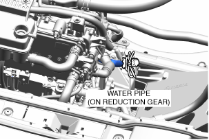
17. Cover and tie the connection hole of the water pipe (on deceleration mechanism) with a plastic bag so that coolant does not leak.
a30zzw00007289
|
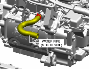
18. Remove the water hose (motor side) from the motor.
a30zzw00007290
|
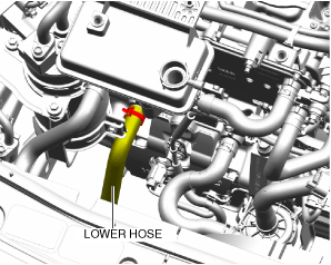
19. Disconnect the lower radiator hose from the motor.
a30zzw00007291
|
20. Remove the coolant temperature sensor. (See COOLANT TEMPERATURE SENSOR REMOVAL/INSTALLATION.)
21. Remove the coolant reserve tank. (See COOLANT RESERVE TANK REMOVAL/INSTALLATION.)
22. Remove the DC-DC converter. (See DC-DC CONVERTER REMOVAL/INSTALLATION.)
23. Disconnect the high voltage cable (junction box No.3 side). (See HIGH VOLTAGE CABLE REMOVAL/INSTALLATION.)
24. Remove the junction box No.3. (See JUNCTION BOX No.3 REMOVAL/INSTALLATION.)
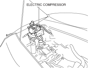
25. Remove the A/C compressor with the A/C hoses and the pipes connected, and secure it using wire or rope so that it does not interfere with the work. (See ELECTRIC COMPRESSOR REMOVAL/INSTALLATION.)
a30zzw00007292
|
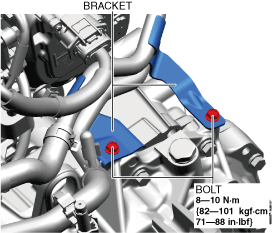
26. Remove the bolts shown in the figure and set the brackets aside.
a30zzw00007293
|
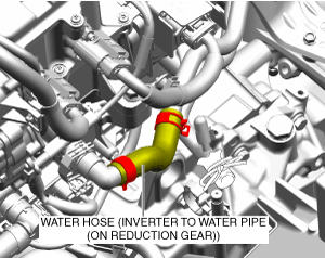
27. Remove the water hose (water pipe (on deceleration mechanism) from inverter).
a30zzw00007294
|
28. Cover and tie the connection hole of the water pipe (on deceleration mechanism) with a plastic bag so that coolant does not leak.
a30zzw00007295
|
29. Remove the inverter. (See INVERTER REMOVAL/INSTALLATION.)
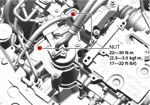
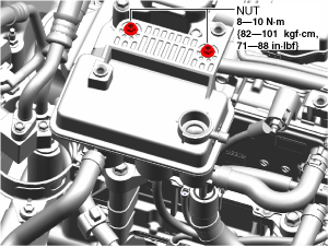
30. Remove the nuts shown in the figure and set the accumulator aside so that it does not interfere with the work. (See ACCUMULATOR REMOVAL/INSTALLATION.)
a30zzw00007296
|
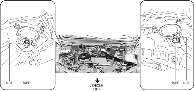
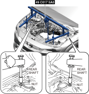
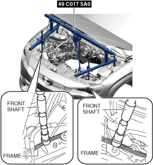
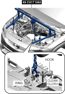
31. Install the SST using the following procedure.
a30zzw00002206
|
a30zzw00002207
|
a30zzw00004528
|
a30zzw00004529
|
a30zzw00004530
|
32. Remove the No.3 mount. (See MOUNT DISASSEMBLY/ASSEMBLY.)
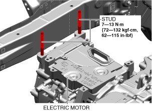
33. Remove the studs from the electric motor.
a30zzw00004531
|
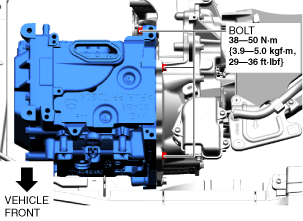
34. Remove the bolts shown in the figure.
a30zzw00004532
|
35. While loosening the SST (49 C017 5A0) chain, tilt the motor to the position away from the front side frame.
36. Lift up the vehicle.
37. Support the electric motor on a jack.
a30zzw00004533
|
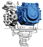
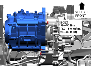
38. Remove the bolts shown in the figure.
a30zzw00004534
|
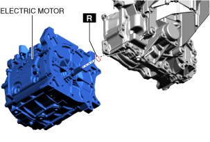
39. Remove the electric motor.
a30zzw00004535
|
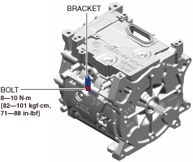
40. Remove the bolt shown in the figure and remove the bracket.
a30zzw00004138
|
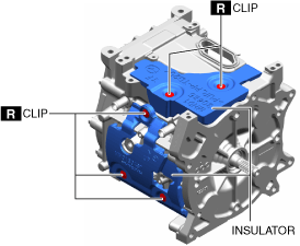
41. Remove the clips shown in the figure and remove the insulator.
a30zzw00004536
|
a30zzw00004537
|
Motor Installation
1. Replace the transaxle oil seals (LH/RH). (See OIL SEAL (DIFFERENTIAL) REPLACEMENT [A71M].)
2. Install in the reverse order of removal.
Coolant Replenishment Procedure
1. Remove the coolant reserve tank installation nuts.
a30zzw00007297
|
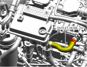
2. Remove the coolant reserve tank outlet hose from the DC-DC converter.
a30zzw00007298
|
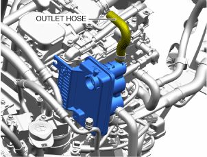
3. Tilt and secure the coolant reserve tank so that the coolant reserve tank outlet hose is pointed upward.
a30zzw00007299
|
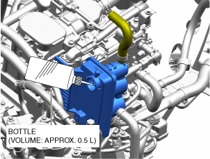
4. Using a commercially-available bottle (volume: approx. 0.5 L), slowly add coolant to the coolant reserve tank.
a30zzw00007347
|
5. Stop adding coolant if it begins accumulating in the coolant reserve tank.
6. Install the coolant reserve tank outlet hose.
a30zzw00007298
|
7. Install the coolant reserve tank installation nuts.
a30zzw00007297
|
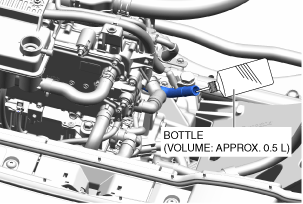
8. Using a commercially-available bottle (volume: approx. 0.5 L), add coolant to the water pipe (on deceleration mechanism).
a30zzw00007348
|
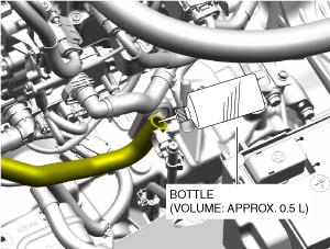
9. Using a commercially-available bottle (volume: approx. 0.5 L), add coolant to the water hose (onboard charger side).
a30zzw00007349
|
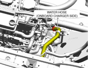
10. Install the water hose (onboard charger side).
a30zzw00007300
|
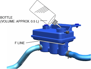
11. Using a commercially-available bottle (volume: approx. 0.5 L), add coolant to the F line on the coolant reserve tank.
a30zzw00007350
|
12. After adding coolant to the F line on the coolant reserve tank, add an additional 0.26 L.
13. Install the cooling system cap.
Operation After Motor Installation
1. Wear insulating gloves and follow the procedure below to install the service plug.
a30zzw00004141
|
a30zzw00004142
|
a30zzw00004143
|
2. Install the service hole cover.
a30zzw00004122
|
3. Close the cover.
a30zzw00004144
|
4. Connect the negative lead-acid battery terminal. (See NEGATIVE LEAD-ACID BATTERY TERMINAL DISCONNECTION/CONNECTION.)
Air Bleeding Procedure
1. Implement [Air Bleeding Procedure] for the coolant replacement. (See COOLANT REPLACEMENT.)
2. Inspect to confirm that there is no coolant leakage at any part. (See COOLANT LEAKAGE INSPECTION.)
3. Install the insulator.
a30zzw00007284
|
4. Install front under cover No.2. (See FRONT UNDER COVER No.2 REMOVAL/INSTALLATION.)
5. Lower the vehicle to the ground and adjust the coolant amount to the F line on the coolant reserve tank.
6. Install the seal cover. (See SEAL COVER REMOVAL/INSTALLATION.)