 |
ac5uuw00007962
ACCELERATOR PEDAL POSITION (APP) SENSOR INSPECTION
id304000100600
Function Inspection
1. Connect the M-MDS to the DLC-2.
2. Switch the main power ON (READY off).
3. Display PCM PIDs [APP1] and [APP2].
(See PID/DATA MONITOR INSPECTION.) (See PID/DATA MONITOR TABLE [PCM (e-SKYACTIV (E))].)
4. Compare the voltage and opening angle indications for PIDs [APP1] and [APP2] with the standard in the table indicated below.
Standard
|
Condition |
APP1 |
APP2 |
||
|---|---|---|---|---|
|
V |
% |
V |
% |
|
|
Accelerator pedal released
|
Approx. 0.75
|
Approx. 15
|
Approx. 0.38
|
Approx. 7.45
|
|
Accelerator pedal depressed
|
Approx. 4.52
|
Approx. 90.58
|
Approx. 2.26
|
Approx. 45.49
|
Voltage inspection
1. Connect the M-MDS to the DLC-2.
2. Switch the main power to ACC or ON (READY off).
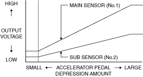
3. Verify that the accelerator pedal position sensor output voltage (PCM PIDs: [APP1], [APP2]) increases smoothly according to the accelerator pedal depression amount when the accelerator pedal is gradually depressed.
(See PID/DATA MONITOR INSPECTION.) (See PID/DATA MONITOR TABLE [PCM (e-SKYACTIV (E))].)
4. Verify that the accelerator pedal position sensor output voltage (PIDs: [APP1], [APP2]) is within the standard when the accelerator pedal is depressed and not depressed.
(See PID/DATA MONITOR INSPECTION.) (See PID/DATA MONITOR TABLE [PCM (e-SKYACTIV (E))].)
Characteristic graph
ac5uuw00007962
|