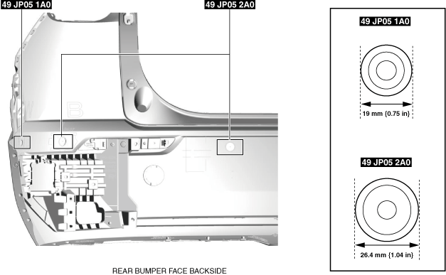
49 JP05 1A0
Hole cutter set 19 (component part for 49 JP05 0A0)

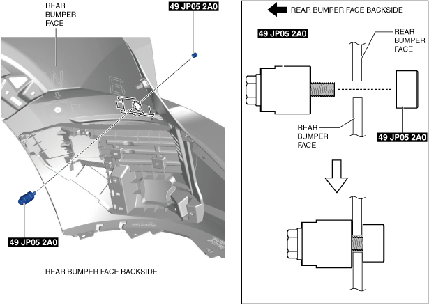
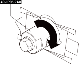
49 JP05 2A0
Hole cutter set 26 (component part for 49 JP05 0A0)

REAR BUMPER DISASSEMBLY/ASSEMBLY
id091000041400
Special service tool (SST)
|
49 JP05 1A0
Hole cutter set 19 (component part for 49 JP05 0A0)
|
|
49 JP05 2A0
Hole cutter set 26 (component part for 49 JP05 0A0)
|
|
Replacement parts
|
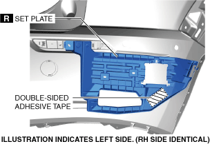
Set plate
Quantity: 2
Location of use: Rear bumper face
|
Rivet
Quantity: 4
Location of use: Set plate
|
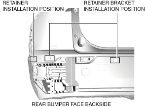
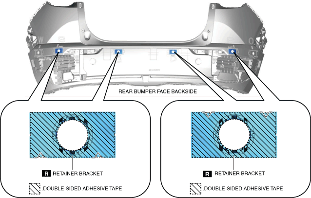
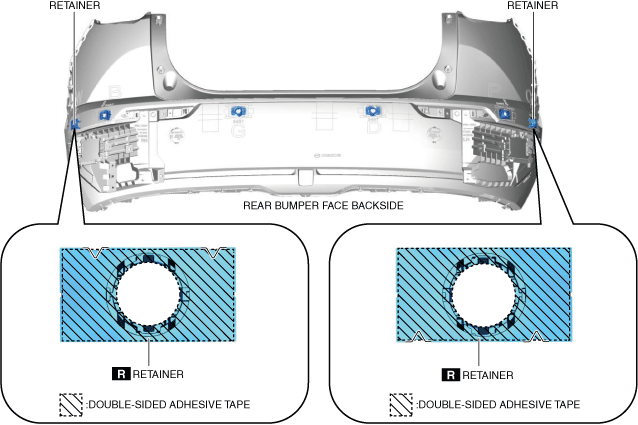
Retainer bracket
Quantity: 4
Location of use: Rear bumper face
|
|
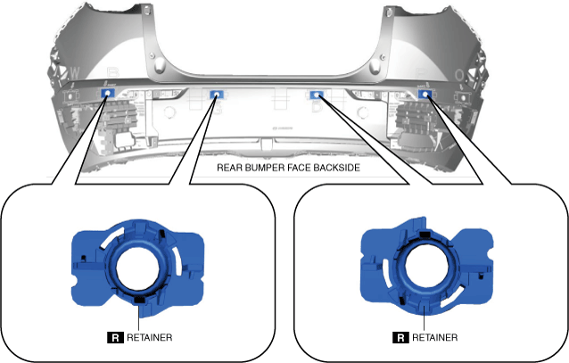
Retainer
Quantity: 6
Location of use: Rear bumper face
|
—
|
—
|
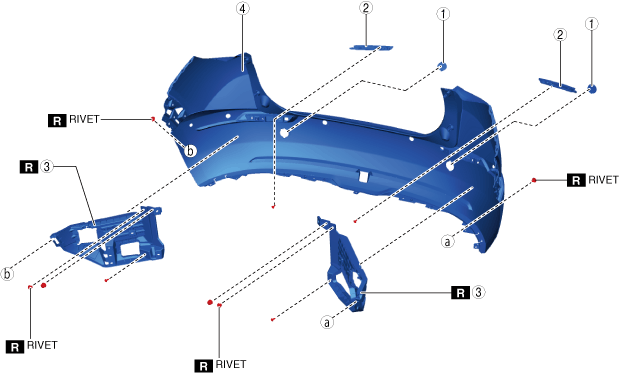
1. Remove the following parts:
2. Disassemble in the order shown in the figure.
a30zzw00000472
|
a30zzw00000473
|
|
1
|
Towing hook cover
|
|
2
|
Rear reflector
|
|
3
|
Set plate
(See Set Plate Installation Note.)
(See Rivet Removal Note.)
|
|
4
|
Rear bumper face
|
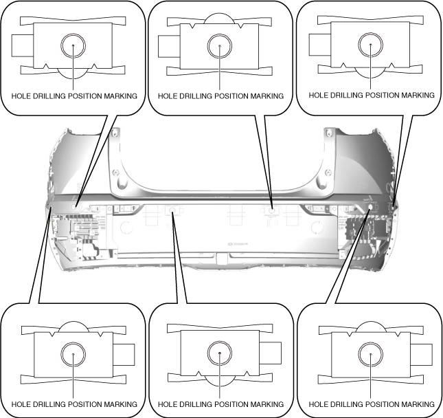
3. When replacing the rear bumper face, perform the following procedure for a new rear bumper face.
a30zzw00000474
|
a30zzw00003030
|
a30zzw00000476
|
a30zzw00000477
|
a30zzw00000478
|
a30zzw00000479
|
a30zzw00004359
|
a30zzw00005895
|
4. Assemble in the reverse order of disassembly.
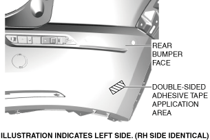
Set Plate Installation Note
1. Remove any grease or dirt on the double-sided adhesive tape application areas.
a30zzw00000481
|
2. Remove the tape backing from the double-sided adhesive tape on the set plate and install the set plate.
a30zzw00000472
|
3. Hold down the part of the set plate with double-sided adhesive tape.
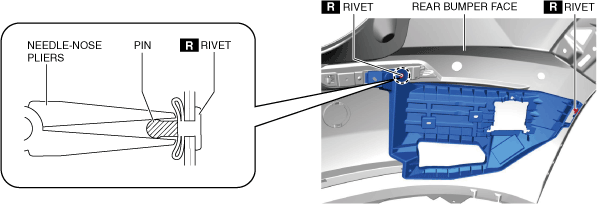
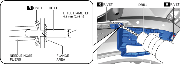
Rivet Removal Note
1. Remove the rivet using the following procedure:
a30zzw00000482
|
a30zzw00000483
|