 |
a30zzw00005639
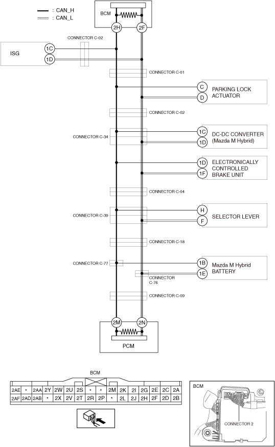
DETERMINING SHORT TO POWER SUPPLY LOCATION (CAN-BUS No.2)
id100200002300
System Wiring Diagram
a30zzw00005639
|
Determination Procedure
|
Step |
Inspection |
Action |
|
|---|---|---|---|
|
1
|
INSPECT BODY CONTROL MODULE (BCM) FOR SHORT TO POWER SUPPLY
• Switch the ignition off.
• Disconnect the negative battery terminal.
• Disconnect the connector 2 which has body control module (BCM) terminals 2H and 2F.
• Connect the negative battery terminal.
• Switch the ignition ON (engine off).
• Measure the voltage at body control module (BCM) terminals 2H and 2F (wiring harness side).
• Is the voltage between 1.5—3.5 V?
|
Yes
|
Replace the body control module (BCM) because there is a short to the power supply in the body control module (BCM).
|
|
No
|
Go to the next step.
|
||
|
2
|
INSPECT CAN LINE BETWEEN BODY CONTROL MODULE (BCM) AND CONNECTOR C-01 FOR SHORT TO POWER SUPPLY
• Switch the ignition off.
• Disconnect the negative battery terminal.
• Disconnect the connector C-01.
• Connect the connector 2 which has body control module (BCM) terminals 2H and 2F.
• Connect the negative battery terminal.
• Switch the ignition ON (engine off).
• Measure the voltage at body control module (BCM) terminals 2H and 2F.
• Is the voltage between 1.5—3.5 V?
|
Yes
|
Go to Step 5.
|
|
No
|
Go to the next step.
|
||
|
3
|
INSPECT CAN LINE BETWEEN INTEGRATED STARTER GENERATOR (ISG) AND CONNECTOR C-02 FOR SHORT TO POWER SUPPLY
• Switch the ignition off.
• Disconnect the negative battery terminal.
• Disconnect the connector C-02.
• Connect the connector C-01.
• Connect the negative battery terminal.
• Switch the ignition ON (engine off).
• Measure the voltage at body control module (BCM) terminals 2H and 2F.
• Is the voltage between 1.5—3.5 V?
|
Yes
|
Go to the next step.
|
|
No
|
Repair or replace the wiring harness between the body control module (BCM) and connector C-01, C-02 because the wiring harness is shorted to the power supply.
|
||
|
4
|
INSPECT INTEGRATED STARTER GENERATOR (ISG) FOR SHORT TO POWER SUPPLY
• Switch the ignition off.
• Disconnect the negative battery terminal.
• Disconnect the integrated starter generator (ISG) connector.
• Connect the connector C-02.
• Connect the negative battery terminal.
• Switch the ignition ON (engine off).
• Measure the voltage at body control module (BCM) terminals 2H and 2F.
• Is the voltage between 1.5—3.5 V?
|
Yes
|
Replace the integrated starter generator (ISG) because there is a short to the power supply in the integrated starter generator (ISG).
|
|
No
|
Repair or replace the wiring harness between the integrated starter generator (ISG) and connector C-02 because the wiring harness is shorted to the power supply.
|
||
|
5
|
INSPECT CAN LINE BETWEEN CONNECTOR C-02 AND CONNECTOR C-01 FOR SHORT TO POWER SUPPLY
• Switch the ignition off.
• Disconnect the negative battery terminal.
• Disconnect the connector C-02.
• Connect the connector C-01.
• Connect the negative battery terminal.
• Switch the ignition ON (engine off).
• Measure the voltage at body control module (BCM) terminals 2H and 2F.
• Is the voltage between 1.5—3.5 V?
|
Yes
|
Go to Step 7.
|
|
No
|
Go to the next step.
|
||
|
6
|
INSPECT PARKING LOCK ACTUATOR FOR SHORT TO POWER SUPPLY
• Switch the ignition off.
• Disconnect the negative battery terminal.
• Disconnect the parking lock actuator.
• Connect the connector C-02.
• Connect the negative battery terminal.
• Switch the ignition ON (engine off).
• Measure the voltage at body control module (BCM) terminals 2H and 2F.
• Is the voltage between 1.5—3.5 V?
|
Yes
|
Replace the parking lock actuator because there is a short to the power supply in the parking lock actuator.
|
|
No
|
Repair or replace the wiring harness between the parking lock actuator and connector C-01, C-02 because the wiring harness is shorted to the power supply.
|
||
|
7
|
INSPECT CAN LINE BETWEEN CONNECTOR C-34 AND CONNECTOR C-02 FOR SHORT TO POWER SUPPLY
• Switch the ignition off.
• Disconnect the negative battery terminal.
• Disconnect the connector C-34.
• Connect the connector C-02.
• Connect the negative battery terminal.
• Switch the ignition ON (engine off).
• Measure the voltage at body control module (BCM) terminals 2H and 2F.
• Is the voltage between 1.5—3.5 V?
|
Yes
|
Go to the next step.
|
|
No
|
Repair or replace the wiring harness between the connector C-34 and connector C-02 because the wiring harness is shorted to the power supply.
|
||
|
8
|
INSPECT CAN LINE BETWEEN DC-DC CONVERTER (Mazda M Hybrid) AND CONNECTOR C-34 FOR SHORT TO POWER SUPPLY
• Measure the voltage at DC-DC converter (Mazda M Hybrid) terminals 1C and 1D.
• Is the voltage between 1.5—3.5 V?
|
Yes
|
Go to Step 10.
|
|
No
|
Go to the next step.
|
||
|
9
|
INSPECT DC-DC CONVERTER (Mazda M Hybrid) FOR SHORT TO POWER SUPPLY
• Switch the ignition off.
• Disconnect the negative battery terminal.
• Disconnect the DC-DC converter (Mazda M Hybrid).
• Connect the connector C-34.
• Connect the negative battery terminal.
• Switch the ignition ON (engine off).
• Measure the voltage at body control module (BCM) terminals 2H and 2F.
• Is the voltage between 1.5—3.5 V?
|
Yes
|
Replace the DC-DC converter (Mazda M Hybrid) because there is a short to the power supply in the DC-DC converter (Mazda M Hybrid).
|
|
No
|
Repair or replace the wiring harness between the DC-DC converter (Mazda M Hybrid) and connector C-34 because the wiring harness is shorted to the power supply.
|
||
|
10
|
INSPECT CAN LINE BETWEEN CONNECTOR C-34 AND CONNECTOR C-04 FOR SHORT TO POWER SUPPLY
• Switch the ignition off.
• Disconnect the negative battery terminal.
• Disconnect the connector C-04.
• Connect the connector C-34.
• Connect the negative battery terminal.
• Switch the ignition ON (engine off).
• Measure the voltage at body control module (BCM) terminals 2H and 2F.
• Is the voltage between 1.5—3.5 V?
|
Yes
|
Go to Step 12.
|
|
No
|
Go to the next step.
|
||
|
11
|
INSPECT ELECTRONICALLY CONTROLLED BRAKE UNIT FOR SHORT TO POWER SUPPLY
• Switch the ignition off.
• Disconnect the negative battery terminal.
• Disconnect the electronically controlled brake unit connector.
• Connect the connector C-04.
• Connect the negative battery terminal.
• Switch the ignition ON (engine off).
• Measure the voltage at body control module (BCM) terminals 2H and 2F.
• Is the voltage between 1.5—3.5 V?
|
Yes
|
Replace the electronically controlled brake unit because there is a short to the power supply in the electronically controlled brake unit.
|
|
No
|
Repair or replace the wiring harness between the electronically controlled brake unit and connector C-04, C-34 because the wiring harness is shorted to the power supply.
|
||
|
12
|
INSPECT CAN LINE BETWEEN CONNECTOR C-39 AND CONNECTOR C-04 FOR SHORT TO POWER SUPPLY
• Switch the ignition off.
• Disconnect the negative battery terminal.
• Disconnect the connector C-39.
• Connect the connector C-04.
• Connect the negative battery terminal.
• Switch the ignition ON (engine off).
• Measure the voltage at body control module (BCM) terminals 2H and 2F.
• Is the voltage between 1.5—3.5 V?
|
Yes
|
Go to the next step.
|
|
No
|
Repair or replace the wiring harness between the connector C-39 and connector C-04 because the wiring harness is shorted to the power supply.
|
||
|
13
|
INSPECT CAN LINE BETWEEN SELECTOR LEVER AND CONNECTOR C-39 FOR SHORT TO POWER SUPPLY
• Measure the voltage at selector lever terminals H and F.
• Is the voltage between 1.5—3.5 V?
|
Yes
|
Go to Step 15.
|
|
No
|
Go to the next step.
|
||
|
14
|
INSPECT SELECTOR LEVER FOR SHORT TO POWER SUPPLY
• Switch the ignition off.
• Disconnect the negative battery terminal.
• Disconnect the selector lever connector.
• Connect the connector C-39.
• Connect the negative battery terminal.
• Switch the ignition ON (engine off).
• Measure the voltage at body control module (BCM) terminals 2H and 2F.
• Is the voltage between 1.5—3.5 V?
|
Yes
|
Replace the selector lever because there is a short to the power supply in the selector lever.
|
|
No
|
Repair or replace the wiring harness between the selector lever and connector C-39 because the wiring harness is shorted to the power supply.
|
||
|
15
|
INSPECT CAN LINE BETWEEN CONNECTOR C-39 AND CONNECTOR C-18 FOR SHORT TO POWER SUPPLY
• Switch the ignition off.
• Disconnect the negative battery terminal.
• Disconnect the connector C-18.
• Connect the connector C-39.
• Connect the negative battery terminal.
• Switch the ignition ON (engine off).
• Measure the voltage at body control module (BCM) terminals 2H and 2F.
• Is the voltage between 1.5—3.5 V?
|
Yes
|
Go to the next step.
|
|
No
|
Repair or replace the wiring harness between the connector C-39 and connector C-18 because the wiring harness is shorted to the power supply.
|
||
|
16
|
INSPECT CAN LINE BETWEEN CONNECTORS C-77, C-76 AND CONNECTOR C-18 FOR SHORT TO POWER SUPPLY
• Switch the ignition off.
• Disconnect the negative battery terminal.
• Disconnect the connectors C-77, C-76.
• Connect the connector C-18.
• Connect the negative battery terminal.
• Switch the ignition ON (engine off).
• Measure the voltage at body control module (BCM) terminals 2H and 2F.
• Is the voltage between 1.5—3.5 V?
|
Yes
|
Go to the next step.
|
|
No
|
Repair or replace the wiring harness between the connectors C-77, C-76 and connector C-18 because the wiring harness is shorted to the power supply.
|
||
|
17
|
INSPECT CAN LINE BETWEEN Mazda M Hybrid BATTERY AND CONNECTORS C-77, C-76 FOR SHORT TO POWER SUPPLY
• Measure the voltage at Mazda M Hybrid battery terminals 1B and 1E.
• Is the voltage between 1.5—3.5 V?
|
Yes
|
Go to Step 19.
|
|
No
|
Go to the next step.
|
||
|
18
|
INSPECT Mazda M Hybrid BATTERY FOR SHORT TO POWER SUPPLY
• Switch the ignition off.
• Disconnect the negative battery terminal.
• Disconnect the Mazda M Hybrid battery connector.
• Connect the connectors C-77, C-76.
• Connect the negative battery terminal.
• Switch the ignition ON (engine off).
• Measure the voltage at body control module (BCM) terminals 2H and 2F.
• Is the voltage between 1.5—3.5 V?
|
Yes
|
Replace the Mazda M Hybrid battery because there is a short to the power supply in the Mazda M Hybrid battery.
|
|
No
|
Repair or replace the wiring harness between the Mazda M Hybrid battery and connectors C-77, C-76 because the wiring harness is shorted to the power supply.
|
||
|
19
|
INSPECT CAN LINE BETWEEN CONNECTOR C-09 AND CONNECTORS C-77, C-76 FOR SHORT TO POWER SUPPLY
• Switch the ignition off.
• Disconnect the negative battery terminal.
• Disconnect the connector C-09.
• Connect the connectors C-77, C-76.
• Connect the negative battery terminal.
• Switch the ignition ON (engine off).
• Measure the voltage at body control module (BCM) terminals 2H and 2F.
• Is the voltage between 1.5—3.5 V?
|
Yes
|
Go to the next step.
|
|
No
|
Repair or replace the wiring harness between the connector C-09 and connectors C-77, C-76 because the wiring harness is shorted to the power supply.
|
||
|
20
|
INSPECT PCM FOR SHORT TO POWER SUPPLY
• Switch the ignition off.
• Disconnect the negative battery terminal.
• Disconnect the PCM connector.
• Connect the connector C-09.
• Connect the negative battery terminal.
• Switch the ignition ON (engine off).
• Measure the voltage at body control module (BCM) terminals 2H and 2F.
• Is the voltage between 1.5—3.5 V?
|
Yes
|
Replace the PCM because there is a short to the power supply in the PCM.
|
|
No
|
Repair or replace the wiring harness between the PCM and connector C-09 because the wiring harness is shorted to the power supply.
|
||