Diagnostic procedure
|
STEP
|
INSPECTION
|
ACTION
|
|
|---|---|---|---|
|
1
|
INSPECT THE FUSE
• Remove the RHT L 30 A and RHT R 30 A fuse.
• Is the fuse normal?
|
Yes
|
Go to the next step.
|
|
No
|
Replace the fuse.
|
||
|
2
|
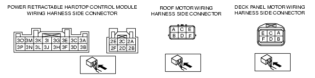
INSPECT THE WIRING HARNESS BETWEEN BATTERY AND POWER RETRACTABLE HARDTOP CONTROL MODULE
• Turn the ignition switch to the ON position.
• Refer to the power retractable hardtop control module inspection and measure the voltage between power retractable hardtop control module connector terminals 2A and 2B.
• Are the terminal voltages normal?
|
Yes
|
Go to the next step.
|
|
No
|
Repair or replace the wiring harness.
|
||
|
3
|
INSPECT THE WIRING HARNESS BETWEEN POWER RETRACTABLE HARDTOP CONTROL MODULE AND GROUND
• Turn the ignition switch to the LOCK position.
• Disconnect the negative battery cable.
• Disconnect the power retractable hardtop control module connector.
• Inspect for continuity between power retractable hardtop control module terminal 2E and body ground, and terminal 2F and body ground.
• Is there continuity?
|
Yes
|
Go to the next step.
|
|
No
|
Repair or replace the wiring harness.
|
||
|
4
|
INSPECT THE ROOF/DECK PANEL MOTOR
• Inspect the roof/deck panel motor.
(See ROOF MOTOR INSPECTION.)
(See DECK PANEL MOTOR INSPECTION.)
• Is the roof/deck panel motor normal?
|
Yes
|
Go to the next step.
|
|
No
|
Replace the roof/deck panel motor.
|
||
|
5
|
INSPECT THE WIRING HARNESS BETWEEN ROOF/DECK PANEL MOTOR AND POWER RETRACTABLE HARDTOP CONTROL MODULE
• Disconnect the roof/deck panel motor connector.
• Disconnect the power retractable hardtop control module connector.
• Inspect the following wiring harnesses for an open or short circuit.
• Is the wiring harness normal?
|
Yes
|
Replace the power retractable hardtop control module.
|
|
No
|
Repair or replace the wiring harness.
|
||