|
1
|
VERIFY FREEZE FRAME DATA (MODE 12) AND DIAGNOSTIC MONITORING TEST RESULTS HAVE BEEN RECORDED
• Have the FREEZE FRAME DATA (Mode 12) and DIAGNOSTIC MONITORING TEST RESULTS (A/F sensor, HO2S related) been recorded?
|
Yes
|
Go to the next step.
|
|
No
|
Record the FREEZE FRAME DATA (Mode 12) and DIAGNOSTIC MONITORING TEST RESULTS on repair order, then go to the next step.
|
|
2
|
VERIFY RELATED SERVICE INFORMATION AVAILABILITY
• Verify related Service Information availability.
• Is any related Service Information available?
|
Yes
|
Perform repair or diagnosis according to the available Service Information.
• If the vehicle is not repaired, go to the next step.
|
|
No
|
Go to the next step.
|
|
3
|
VERIFY RELATED PENDING CODE AND STORED DTC
-
Note
-
• If the fuel monitor DTC, DTC P0132 is retrieved, ignore it until P0140 is fixed.
• Turn the ignition switch off, then to the ON position. (engine off)
• Perform the Pending Trouble Code Access Procedure and DTC Reading Procedure.
• Are any DTCs present?
|
Yes
|
Go to the applicable DTC troubleshooting.
|
|
No
|
Go to the next step.
|
|
4
|
IDENTIFY TRIGGER DTC FOR FREEZE FRAME DATA (MODE 2)
• Perform the Freeze Frame PID Data Access Procedure.
• Is the DTC P0140 on FREEZE FRAME DATA (Mode 2)?
|
Yes
|
Go to the next step.
|
|
No
|
Go to the DTC troubleshooting on FREEZE FRAME DATA (Mode 2).
|
|
5
|
INSPECT INSTALLATION OF HO2S
• Inspect if the HO2S is loosely installed.
• Is the sensor installed securely?
|
Yes
|
Go to the next step.
|
|
No
|
Retighten the HO2S, then go to Step 15.
|
|
6
|
INSPECT GAS LEAKAGE FROM EXHAUST SYSTEM
• Visually inspect if any gas leakage is found between exhaust pipe and HO2S.
• Is there gas leakage?
|
Yes
|
Repair or replace the malfunctioning part according to the inspection results, then go to Step 15.
|
|
No
|
Go to the next step.
|
|
7
|
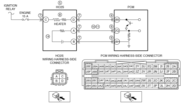
INSPECT HO2S CONNECTOR AND TERMINALS
• Turn the ignition switch off.
• Disconnect the HO2S connector.
• Inspect for poor connection (such as damaged/pulled-out pins, and corrosion).
• Is there any malfunction?
|
Yes
|
Repair or replace the connector or terminals, then go to Step 15.
|
|
No
|
Go to the next step.
|
|
8
|
INSPECT HO2S HEATER
• Inspect the HO2S heater.
• Is there any malfunction?
|
Yes
|
Replace the HO2S, then go to Step 15.
|
|
No
|
Go to the next step.
|
|
9
|
INSPECT PCM CONNECTOR AND TERMINALS
• Disconnect the PCM connector.
• Inspect for poor connection (such as damaged/pulled-out pins, and corrosion).
• Is there any malfunction?
|
Yes
|
Repair or replace the connector or terminals, then go to Step 15.
|
|
No
|
Go to the next step.
|
|
10
|
INSPECT HO2S SIGNAL CIRCUIT FOR SHORT TO GROUND
• HO2S and PCM connectors are disconnected.
• Inspect for continuity between HO2S terminal A (wiring harness-side) and body ground.
• Is there continuity?
|
Yes
|
Repair or replace the wiring harness for a possible short to ground, then go to Step 15.
|
|
No
|
Go to the next step.
|
|
11
|
INSPECT HO2S SIGNAL CIRCUIT FOR OPEN CIRCUIT
• HO2S and PCM connectors are disconnected.
• Inspect for continuity between HO2S terminal A (wiring harness-side) and PCM terminal 2Q.
• Is there continuity?
|
Yes
|
Go to the next step.
|
|
No
|
Repair or replace the wiring harness for a possible open circuit, then go to Step 15.
|
|
12
|
INSPECT SEALING OF ENGINE COOLANT PASSAGE
• Reconnect the HO2S and PCM connectors.
-
Warning
-
• Removing the radiator cap when the radiator is hot is dangerous. Scalding coolant and steam may shoot out and cause serious injury.
• When removing the radiator cap, wrap a thick cloth around and turn it slowly.
• Remove the radiator cap.
• Perform procedure to bleed air from the engine coolant, then run the engine at idle.
• Is there any small bubble, which makes the engine coolant white at filling opening?
-
Note
-
• Large bubbles are normal since they are remaining air coming out from the engine coolant passage.
|
Yes
|
Air gets in from poor sealing on head gasket or other areas between combustion chamber and engine coolant passage.
Repair or replace the malfunctioning part according to the inspection results, then go to Step 15.
|
|
No
|
Go to the next step.
|
|
13
|
INSPECT ENGINE COMPRESSION
• Inspect the engine compression.
• Is there any malfunction?
|
Yes
|
Perform the engine overhaul for repairs, then go to Step 15.
|
|
No
|
Go to the next step.
|
|
14
|
INSPECT HO2S
• Is there any malfunction?
|
Yes
|
Replace the HO2S, then go to the next step.
|
|
No
|
Go to the next step.
|
|
15
|
VERIFY DTC TROUBLESHOOTING COMPLETED
• Make sure to reconnect all disconnected connectors.
• Turn the ignition switch to the ON position. (engine off)
• Clear the DTC from the PCM memory using the M-MDS.
• Perform the KOER self test.
• Is the PENDING CODE for this DTC present?
|
Yes
|
Replace the PCM, then go to the next step.
|
|
No
|
Go to the next step.
|
|
16
|
VERIFY AFTER REPAIR PROCEDURE
• Perform the “AFTER REPAIR PROCEDURE”.
• Are any DTCs present?
|
Yes
|
Go to the applicable DTC troubleshooting.
|
|
No
|
DTC troubleshooting completed.
|