 |
e5u213zw5004
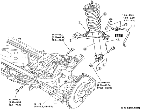
FRONT UPPER ARM REMOVAL/INSTALLATION
id021300801900
1. For 6MT vehicles, perform the following procedures.
2. Remove the front suspension tower bar. (See FRONT SUSPENSION TOWER BAR REMOVAL/INSTALLATION.)
3. Remove in the order indicated in the table.
4. Install in the reverse order of removal.
5. Inspect the front wheel alignment and adjust it if necessary. (See FRONT WHEEL ALIGNMENT.)
e5u213zw5004
|
|
1
|
Brake hose bracket
|
|
2
|
Front upper arm ball joint
|
|
3
|
Front shock absorber, coil spring and front upper arm
|
|
4
|
Front upper arm
(See Front Upper Arm Removal Note.)
|
Front Upper Arm Ball Joint Removal Note
1. Remove the front upper arm ball joint from the steering knuckle using the SST.
amxzzw00000052
|
Front Shock Absorber, Coil Spring And Front Upper Arm Removal Note
1. Loosen the shock absorber upper nuts.
2. Remove the front shock absorber lower bolt and nut.
Front Upper Arm Removal Note
1. Remove the front upper arm bolts.
2. Push down the front lower arm, and then remove the front upper arm from the gap between the shock absorber lower end and the front lower arm.
