STEP
INSPECTION
ACTION
1
INSPECT BRAKE FLUID LEVEL
• Inspect the brake fluid level.
• Is the brake fluid level normal?
Yes
Vehicles without malfunction warning light (Applied VIN (assumed): NC18**215550—, NC18**250831—, NC30**202488—, NCA8**251024—)
Go to the next step.
Others
Go to step 3.
No
Add the brake fluid.
2
CONFIRM PCM DTC
• Perform the Reading DTCs Procedure.
• Is the DTC P0571 and/or P0703 present?
Yes
Go to the applicable DTC inspection.
(See DTC P0571 [L8, LF].)
(See DTC P0703 [L8, LF].)
No
Go to the next step.
*3
INSPECT WIRING HARNESS BETWEEN ABS HU/CM AND DLC-2 FOR CONTINUITY AND SHORTS
• Perform the Reading DTCs Procedure.
(See ON-BOARD DIAGNOSIS [ABS].)
• Is the error message displayed regarding communication between ABS HU/CM and M-MDS?
Yes
If a communication error message is displayed even after inspecting according to the procedure displayed on the M-MDS, go to Step 7.
No
Go to the next step.
4
CONFIRM ABS HU/CM DTC
• Perform the Reading DTCs Procedure.
(See ON-BOARD DIAGNOSIS [ABS].)
• Are any DTC present?
Yes
Go to the applicable DTC inspection.
(See ON-BOARD DIAGNOSIS [ABS].)
No
Go to the next step.
5
INSPECT WARNING LIGHT OPERATION
• Turn on the all warning light on instrument cluster using the instrument cluster input/output check code 26.
• Do the ABS and brake system warning light illuminate?
Yes
Go to the next step.
No
Replace the instrument cluster.
6
VERIFY WHETHER MALFUNCTION IS IN PARKING BRAKE SWITCH OR BRAKE FLUID LEVEL SENSOR, OR IN SOME OTHER PART
• Disconnect the connectors in the following order:
-
1. Parking brake switch connector2. Brake fluid level sensor connector
• Does the brake system warning light go out with ignition switch turned to the ON position?
Yes
Replace the parking brake switch and/or brake fluid level sensor (short with some internal part).
No
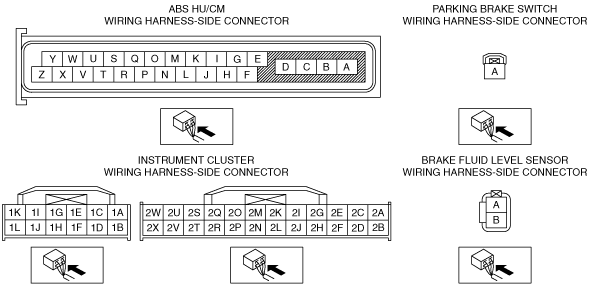
Inspect the wiring harness between the following terminals for short to ground:
• Instrument cluster terminal 2M (brake system warning light) and parking brake switch terminal A
• Instrument cluster terminal 1D (brake system warning light) and brake fluid level sensor terminal A
If the wiring harness has a malfunction:
• Repair or replace the wiring harness for a possible short to ground.
If the wiring harness is normal:
• Replace the ABS HU/CM.
*7
INSPECT WIRING HARNESS BETWEEN ABS HU/CM AND DLC-2 FOR CONTINUITY
• Turn the ignition switch off.
• Inspect for continuity between ABS HU/CM terminal Y, Z and DLC-2 (wiring harness-side).
• Is there continuity?
Yes
Go to the next step.
No
Repair or replace the wiring harness for a possible open circuit.
*8
INSPECT WIRING HARNESS BETWEEN ABS HU/CM AND DLC-2 FOR SHORT TO POWER SUPPLY
• Turn the ignition switch to the ON position (engine off).
• Measure the voltage at ABS HU/CM terminal Y, Z (wiring harness-side).
• Is the voltage approx. 12 V?
Yes
Repair or replace the wiring harness for a possible short to power supply.
No
Go to the next step.
*9
INSPECT WIRING HARNESS BETWEEN ABS HU/CM AND DLC-2 FOR SHORT TO GROUND
• Turn the ignition switch off.
• Inspect for continuity between ABS HU/CM terminal Y, Z (wiring harness-side) and body ground.
• Is there continuity?
Yes
Repair or replace the wiring harness for a possible short to ground.
No
Replace the ABS HU/CM (ABS HU/CM internal communication circuit malfunction).