 |
amxzzw00000860
PID/DATA MONITOR INSPECTION [SJ6A-EL]
id050208805600
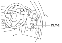
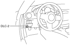
1. Connect the M-MDS to the DLC-2.
L.H.D.
amxzzw00000860
|
R.H.D.
amxzzw00000861
|
2. After the vehicle is identified, select the following items from the initial screen of the M-MDS.
3. Select the PID from the PID table.
4. Verify the PID data according to the directions on the M-MDS screen.
PID/DATA MONITOR AND RECORD function table
|
Monitor item (Definition) |
Unit/Condition |
Condition/Specification |
Action |
TCM terminal |
|---|---|---|---|---|
|
BOO TCM
(Brake switch)
|
On/Off
|
• Brake pedal depressed: On
• Other: Off
|
Inspect the brake switch.
(See BRAKE SWITCH INSPECTION.)
|
N/A
|
|
DTCCNT
|
N/A
|
Indicates number of DTC
|
Check DTC.
(See DTC TABLE [SJ6A-EL].)
|
N/A
|
|
DWN SW
(Down switch)
|
On/Off
|
• Down shift at M range: On
• Other: Off
|
Inspect the selector lever component.
|
2F
|
|
ECT TCM
(ECT)
|
°C
|
Indicates ECT
|
• Inspect the ECT sensor.
• Inspect the PCM.
(See PCM INSPECTION [L8, LF].)
|
N/A
|
|
FDPDTC
(FREEZE FRAME DATA)
|
N/A
|
Indicates code of FREEZE FRAME DATA
|
N/A
|
N/A
|
|
GEAR_RA
(Gear ratio)
|
N/A
|
• 1GR: 3.538
• 2GR: 2.060
• 3GR: 1.404
• 4GR: 1.000
• 5GR: 0.713
• 6GR: 0.582
• R position: 3.168
|
Inspect following PIDs: OSS, SSA, SSB, SSC, SSD, SSE, SSF, SSG, THOP, TSS, VSS
|
N/A
|
|
GEAR_SEL
(Calculated gear range in TCM)
|
1/2/3/4/5/6
|
• 1GR: 1
• 2GR: 2
• 3GR: 3
• 4GR: 4
• 5GR: 5
• 6GR: 6
|
Inspect following PIDs: SSA, SSB, SSC, SSD, SSE, SSF, SSG, THOP, TSS, VSS
|
N/A
|
|
LPS
(Line pressure control solenoid)
|
A
|
• D range, 1GR (idle): 996 mA
• D range, 3GR: 656 mA
• R position: 719 mA
|
Inspect the line pressure control solenoid.
|
1E, 1R
|
|
MNL SW
(M range switch)
|
On/Off
|
• M range: On
• Other: Off
|
Inspect the selector lever component.
|
2G
|
|
OSS
(Output shaft speed)
|
RPM
|
• Vehicle speed 40 km/h {25 mph}: 3,800 RPM
• Indicates output shaft speed
|
Inspect the VSS.
|
2C, 2D
|
|
PNP_TCM
(Park/Neutral)
|
Drive/Neutral
|
• P, N position: Neutral
• D, M range or R position: Drive
|
Inspect the TR switch.
|
2K, 2M, 2N, 2O
|
|
RPM TCM
(Engine speed)
|
RPM
|
• Ignition switch ON: 0 rpm
• Idle: 700—800 rpm
|
• Inspect the CMP sensor.
• Inspect the PCM.
(See PCM INSPECTION [L8, LF].)
|
N/A
|
|
SS SW-
(Steering shift switch (down switch))
|
On/Off
|
M range
• Steering shift down switch on: On
• Other: Off
|
Inspect the steering shift switch.
|
2AB, 2AF
|
|
SS SW+
(Steering shift switch (up switch))
|
On/Off
|
M range
• Steering shift up switch on: On
• Other: Off
|
Inspect the steering shift switch.
|
2AB, 2AF
|
|
SSA
(Shift solenoid A)
|
On/Off
|
• 2GR, 3GR, 4GR, 5GR, 6GR: On
• 1GR: Off
|
Inspect the shift solenoid A.
|
1AF
|
|
SSB
(Shift solenoid B)
|
On/Off
|
• 1GR, 2GR, 6GR: On
• 3GR, 4GR, 5GR: Off
|
Inspect the shift solenoid B.
|
1AB
|
|
SSC
(Shift solenoid C)
|
On/Off
|
• 1GR, 2GR, 3GR: On
• 4GR, 5GR, 6GR: Off
|
Inspect the shift solenoid C.
|
1AA
|
|
SSD
(Shift solenoid D)
|
On/Off
|
• 5GR, 6GR: On
• 1GR, 2GR, 3GR, 4GR: Off
|
Inspect the shift solenoid D.
|
1S
|
|
SSE
(Shift solenoid E)
|
On/Off
|
• 1GR, 2GR, 3GR, 4GR: On
• 5GR, 6GR: Off
|
Inspect the shift solenoid E.
|
1V
|
|
SSF
(Shift solenoid F)
|
A
|
• 5GR, 6GR: 996 mA
• 1GR, 2GR, 3GR, 4GR: 199 mA
|
Inspect the shift solenoid F.
|
1O, 1Z
|
|
SSG
(Shift solenoid G)
|
A
|
• 1GR, 2GR, 3GR, 4GR: 996 mA
• 5GR, 6GR: 199 mA
|
Inspect the shift solenoid G.
|
1L, 1Y
|
|
TCCC
(TCC solenoid valve)
|
A
|
• TCC on: 996 mA
• Other: 199 mA
|
Inspect the TCC control solenoid.
|
1D, 1Q
|
|
TFT
(ATF temperature)
|
°C
|
• ATF temperature 20 °C {68 °F}: 20 °C
• ATF temperature 40 °C {104 °F}: 40 °C
• ATF temperature 60 °C {140 °F}: 60 °C
|
Inspect the TFT sensor.
|
1J, 1M
|
|
TFTV
(ATF temperature signal voltage)
|
V
|
• ATF temperature 20 °C {68 °F}: 3 V
• ATF temperature 40 °C {104 °F}: 2.14 V
• ATF temperature 60 °C {140 °F}: 1.38 V
|
Inspect the TFT sensor.
|
1J, 1M
|
|
THOP
(Throttle position)
|
%
|
• CTP: 20%
• WOT: 89.8%
|
• Inspect the TP sensor.
• Inspect the PCM.
(See PCM INSPECTION [L8, LF].)
|
N/A
|
|
TR
(TR switch)
|
R/N/D/P
|
• R position: R
• N position: N
• D range: D
• P position: P
|
Inspect the TR switch.
|
2K, 2M, 2N, 2O
|
|
TRD
(TR switch [D range])
|
On/Off
|
• D range: On
• Other ranges and all positions: Off
|
Inspect the TR switch.
|
2K
|
|
TRR
(TR switch [R position])
|
On/Off
|
• R position: On
• Other positions and all ranges: Off
|
Inspect the TR switch.
|
2M
|
|
TSS
(Turbine shaft speed)
|
RPM
|
• Idle: 700—800 rpm
• Vehicle speed 40 km/h {25 mph}: 3,800 RPM
|
Inspect the turbine sensor.
|
2A, 2B
|
|
UP SW
(Up switch)
|
On/Off
|
• Up shift at M range: On
• Other: Off
|
Inspect the selector lever component.
|
2J
|
|
VPWR_TCM
(Battery voltage)
|
V
|
Ignition switch at ON position: B+
|
• Inspect the ignition switch.
(See IGNITION SWITCH INSPECTION.)
• Inspect the battery.
(See BATTERY INSPECTION [L8, LF].)
|
1AD
|
|
VSS
(Vehicle speed)
|
KPH
|
• Vehicle speed 40 km/h {25 mph}: 40 KPH
• Indicates vehicle speed
|
Inspect the VSS.
|
2C, 2D
|
Simulation Function Procedure
1. Connect the M-MDS to the DLC-2.
L.H.D.
amxzzw00000860
|
R.H.D.
amxzzw00000861
|
2. After the vehicle is identified, select the following items from the initial screen of the M-MDS.
3. Select the simulation items from the PID table.
4. Perform the simulation function, inspect the operations for each parts.
Simulation item table
|
Simulation item |
Applicable component |
Unit/Condition |
Operation |
TCM terminal |
|
|---|---|---|---|---|---|
|
IG ON |
Idle |
||||
|
LPS
|
Pressure control solenoid
|
A
|
N/A
|
X
|
1E, 1R
|
|
SSA
|
Shift solenoid A
|
On/Off
|
N/A
|
X
|
1AF
|
|
SSB
|
Shift solenoid B
|
On/Off
|
N/A
|
X
|
1AB
|
|
SSC
|
Shift solenoid C
|
On/Off
|
N/A
|
X
|
1AA
|
|
SSD
|
Shift solenoid D
|
On/Off
|
N/A
|
X
|
1S
|
|
SSE
|
Shift solenoid E
|
On/Off
|
N/A
|
X
|
1V
|
|
SSF
|
Shift solenoid F
|
A
|
N/A
|
X
|
1O, 1Z
|
|
SSG
|
Shift solenoid G
|
A
|
N/A
|
X
|
1L, 1Y
|
|
TCCC
|
TCC solenoid valve
|
A
|
N/A
|
X
|
1D, 1Q
|