|
1
|
VERIFY FREEZE FRAME DATA HAS BEEN RECORDED
• Has the FREEZE FRAME DATA been recorded on the repair order?
|
Yes
|
Go to the next step.
|
|
No
|
Record the FREEZE FRAME DATA on the repair order, then go to the next step.
|
|
2
|
VERIFY RELATED REPAIR INFORMATION AVAILABILITY
• Verify related service repair information availability.
• Is any related repair information available?
|
Yes
|
Perform repair or diagnosis according to the available repair information.
• If the vehicle is not repaired, go to the next step.
|
|
No
|
Go to the next step.
|
|
3
|
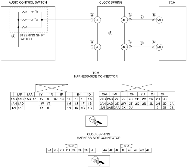
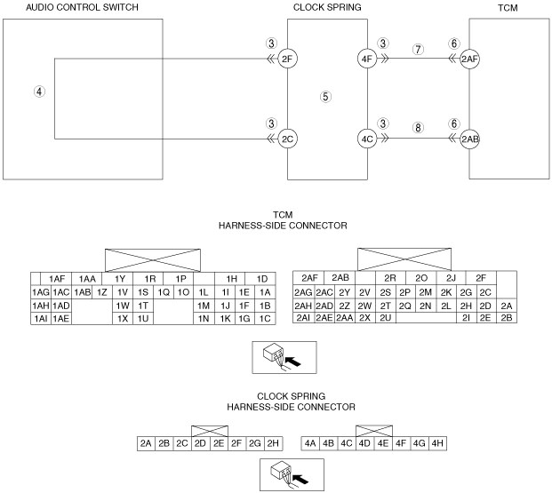
INSPECT CLOCK SPRING CONNECTOR FOR POOR CONNECTION
• Turn the ignition switch to the LOCK position.
• Disconnect the clock spring connector.
• Inspect for poor connection at clock spring terminals 2C, 2F, 4C and 4F (such as damaged/pulled-out pins, corrosion).
• Are the connector and terminals normal?
|
Yes
|
Go to the next step.
|
|
No
|
Repair or replace the connector and/or terminal, then go to Step 9.
|
|
4
|
INSPECT STEERING SHIFT SWITCH
• Inspect the steering shift switch.
• Is the steering shift switch normal?
|
Yes
|
Go to the next step.
|
|
No
|
Replace the steering shift switch, then go to Step 9.
|
|
5
|
INSPECT CLOCK SPRING
• Inspect the clock spring.
• Is the clock spring normal?
|
Yes
|
Go to the next step.
|
|
No
|
Replace the clock spring, then go to Step 9.
|
|
6
|
INSPECT TCM CONNECTOR FOR POOR CONNECTION
• Disconnect the TCM connector.
• Inspect for poor connection at TCM terminals 2AF and 2AB (such as damaged/pulled-out pins, corrosion).
• Are the connector and terminals normal?
|
Yes
|
Go to the next step.
|
|
No
|
Repair or replace the connector and/or terminal, then go to Step 9.
|
|
7
|
INSPECT SIGNAL CIRCUIT FOR OPEN CIRCUIT
• Inspect for continuity between the clock spring (wiring harness-side) terminal 4F and TCM (wiring harness-side) terminal 2AF.
• Is there continuity?
|
Yes
|
Go to the next step.
|
|
No
|
Repair or replace the wiring harness, then go to Step 9.
|
|
8
|
INSPECT GROUND CIRCUIT FOR OPEN CIRCUIT
• Inspect for continuity between the clock spring (wiring harness-side) terminal 4C and TCM (wiring harness-side) terminal 2AB.
• Is there continuity?
|
Yes
|
Go to the next step.
|
|
No
|
Repair or replace the wiring harness, then go to Step 9.
|
|
9
|
VERIFY TROUBLESHOOTING OF DTC P0826 COMPLETED
• Make sure to reconnect all disconnected connectors.
• Clear the DTC using the M-MDS.
• Perform the following procedure to ensure that the DTC has been resolved:
-
1. Start the engine.
2. Idle the engine for 10 s or more.
• Is the same DTC present?
|
Yes
|
Replace the TCM, then go to the next step.
|
|
No
|
Go to the next step.
|
|
10
|
VERIFY NO DTC HAS BEEN PRESENTED
• Perform the “Reading DTCs Procedure”.
• Are any DTCs present?
|
Yes
|
Go to the applicable DTC inspection.
|
|
No
|
DTC troubleshooting completed.
|