DTC P0819:00 [TCM (SJ6A-EL)]
id0502o1822400
DTC P0819:00 |
M position switch up or down switch signal: Signal error |
---|---|
DETECTION CONDITION
|
M position switch signal error
• Vehicle condition: TCM communication normal during engine rotation
• Status: Detects that M position switch is on in P, R or N position
• Period: Confirmed continuously for 2 s
Up switch malfunction or down switch signal error
• Vehicle condition: TCM communication normal during engine rotation
• Status: Detects that up or down switch is on while M position switch is off
• Period: Confirmed continuously for 10 s
|
FAIL-SAFE FUNCTION
|
M position switch signal error
• Inhibits the manual shift control.
• Inhibits manual shifting using the up or down switch of the selector lever.
• Inhibits direct mode.
Up switch malfunction or down switch signal error
• Inhibits manual shifting using the up or down switch of the selector lever.
|
POSSIBLE CAUSE
|
M position switch signal error
• Instrument cluster DTC is stored.
• M position switch malfunction
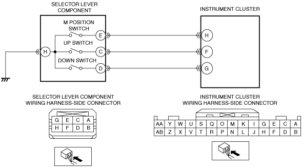
• Short to power supply in wiring harness between selector lever component terminal E and instrument cluster terminal H
• Short to ground in wiring harness between selector lever component terminal E and instrument cluster terminal H
• Open circuit in wiring harness between selector lever component terminal E and instrument cluster terminal H
• Open circuit in wiring harness between selector lever component terminal H and body ground
• TCM connector or terminal malfunction
• Selector lever component connector or terminal malfunction
• TCM malfunction
Up switch malfunction or down switch signal error
• Instrument cluster DTC is stored.
• Up switch malfunction
• Down switch malfunction.
• Short to power supply in wiring harness between selector lever component terminal C and instrument cluster terminal F
• Short to power supply in wiring harness between selector lever component terminal D and instrument cluster terminal G
• Short to ground in wiring harness between selector lever component terminal C and instrument cluster terminal F
• Short to ground in wiring harness between selector lever component terminal D and instrument cluster terminal G
• Open circuit in wiring harness between selector lever component terminal C and instrument cluster terminal F
• Open circuit in wiring harness between selector lever component terminal D and instrument cluster terminal G
• Open circuit in wiring harness between selector lever component terminal H and body ground
• TCM connector or terminal malfunction
• Selector lever component connector or terminal malfunction
• Instrument cluster malfunction
|
![]() |
Diagnostic procedure
STEP |
INSPECTION |
ACTION |
|
---|---|---|---|
1
|
VERIFY RELATED SERVICE INFORMATION AVAILABILITY
• Verify related Service Information availability.
• Is any related Service Information available?
|
Yes
|
Perform repair or diagnosis according to the available Service Information.
• If the vehicle is not repaired, go to the next step.
|
No
|
Go to the next step.
|
||
2
|
CONFIRM INSTRUMENT CLUSTER DTC
• Perform the instrument cluster DTC inspection using the M-MDS.
• Are any DTCs present?
|
Yes
|
Go to the applicable DTC inspection.
|
No
|
Go to the next step.
|
||
3
|
INSPECT SELECTOR LEVER COMPONENT CONNECTOR CONDITION
• Switch the ignition off.
• Disconnect the selector lever component connector.
• Inspect for poor connection (such as damaged/pulled-out pins, corrosion).
• Is there any malfunction?
|
Yes
|
Repair or replace the connector and/or terminals, then go to Step 11.
|
No
|
Go to the next step.
|
||
4
|
INSPECT SELECTOR LEVER COMPONENT
• Inspect the M position switch, up switch and down switch.
• Is there any malfunction?
|
Yes
|
Replace the selector lever component, then go to Step 11.
|
No
|
Go to the next step.
|
||
5
|
INSPECT SELECTOR LEVER COMPONENT GROUND CIRCUIT FOR OPEN CIRCUIT
• Verify that the selector lever component connector is disconnected.
• Inspect for continuity between selector lever component terminal H (wiring harness-side) and body ground.
• Is there continuity?
|
Yes
|
Go to the next step.
|
No
|
Refer to the wiring diagram and verify whether or not there is a common connector between selector lever component terminal H and body ground.
If there is a common connector:
• Determine the malfunctioning part by inspecting the common connector and the terminal for corrosion, damage, or pin disconnection, and the common wiring harness for an open circuit.
• Repair or replace the malfunctioning part.
If there is no common connector:
• Repair or replace the wiring harness which has an open circuit.
Go to Step 11.
|
||
6
|
INSPECT INSTRUMENT CLUSTER CONNECTOR CONDITION
• Disconnect the instrument cluster connector.
• Inspect for poor connection (such as damaged/pulled-out pins, corrosion).
• Is there any malfunction?
|
Yes
|
Repair or replace the connector and/or terminals, then go to Step 11.
|
No
|
Go to the next step.
|
||
7
|
INSPECT SELECTOR LEVER COMPONENT CIRCUIT FOR SHORT TO GROUND
• Verify that the selector lever component and instrument cluster connectors are disconnected.
• Inspect for continuity between the following terminals (wiring harness-side) and body ground:
• Is there continuity?
|
Yes
|
Refer to the wiring diagram and verify whether or not there is a common connector between the following terminals:
• Selector lever component terminal E—Instrument cluster terminal H
• Selector lever component terminal C—Instrument cluster terminal F
• Selector lever component terminal D—Instrument cluster terminal G
If there is a common connector:
• Determine the malfunctioning part by inspecting the common connector and the terminal for corrosion, damage, or pin disconnection, and the common wiring harness for a short to ground.
• Repair or replace the malfunctioning part.
If there is no common connector:
• Repair or replace the wiring harness which has a short to ground.
Go to Step 11.
|
No
|
Go to the next step.
|
||
8
|
INSPECT SELECTOR LEVER COMPONENT CIRCUIT FOR SHORT TO POWER SUPPLY
• Verify that the selector lever component and instrument cluster connectors are disconnected.
• Switch the ignition ON (engine on).
• Measure the voltage at the following terminals (wiring harness-side):
• Is the voltage 0 V?
|
Yes
|
Go to the next step.
|
No
|
Refer to the wiring diagram and verify whether or not there is a common connector between the following terminals:
• Selector lever component terminal E—Instrument cluster terminal H
• Selector lever component terminal C—Instrument cluster terminal F
• Selector lever component terminal D—Instrument cluster terminal G
If there is a common connector:
• Determine the malfunctioning part by inspecting the common connector and the terminal for corrosion, damage, or pin disconnection, and the common wiring harness for a short to power supply.
• Repair or replace the malfunctioning part.
If there is no common connector:
• Repair or replace the wiring harness which has a short to power supply.
Go to Step 11.
|
||
9
|
INSPECT SELECTOR LEVER COMPONENT CIRCUIT FOR OPEN CIRCUIT
• Verify that the selector lever component and instrument cluster connectors are disconnected.
• Switch the ignition off.
• Inspect for continuity between the following terminals (wiring harness-side):
• Is there continuity?
|
Yes
|
Go to the next step.
|
No
|
Refer to the wiring diagram and verify whether or not there is a common connector between the following terminals:
• Selector lever component terminal E—Instrument cluster terminal H
• Selector lever component terminal C—Instrument cluster terminal F
• Selector lever component terminal D—Instrument cluster terminal G
If there is a common connector:
• Determine the malfunctioning part by inspecting the common connector and the terminal for corrosion, damage, or pin disconnection, and the common wiring harness for an open circuit.
• Repair or replace the malfunctioning part.
If there is no common connector:
• Repair or replace the wiring harness which has an open circuit.
Go to Step 11.
|
||
10
|
INSPECT INSTRUMENT CLUSTER
• Inspect the instrument cluster.
• Is there any malfunction?
|
Yes
|
Replace the instrument cluster, then go to the next step.
|
No
|
Go to the next step.
|
||
11
|
VERIFY DTC TROUBLESHOOTING COMPLETED
• Always reconnect all disconnected connectors.
• Clear the DTC using the M-MDS.
• Perform the following procedure to ensure that the DTC has been resolved:
• Perform the DTC inspection using the M-MDS.
• Are any DTCs present?
|
Yes
|
Go to the applicable DTC inspection.
|
No
|
DTC troubleshooting completed.
|