ELECTRIC AT OIL PUMP REMOVAL/INSTALLATION [SJ6A-EL]
id051311117600
-
Caution
-
• Foreign matter in the electric AT oil pump and transmission may cause a malfunction. Perform the following procedures before replacing the electric AT oil pump to prevent foreign matter from entering the AT oil pump and transmission.
-
― Clean the outside of the transmission using steam or detergent oil.
― Verify that there is no foreign matter on the hand of the person servicing the vehicle.
• Do not drop or apply a shock to the electric AT oil pump. Replace the electric AT oil pump if it has been dropped or received an impact.
1. Disconnect the negative battery terminal. (See NEGATIVE BATTERY TERMINAL DISCONNECTION/CONNECTION.)
2. Remove the selector lever knob. (See AUTOMATIC TRANSMISSION SHIFT MECHANISM REMOVAL/INSTALLATION.)
3. Remove the shift panel component. (See SHIFT PANEL REMOVAL/INSTALLATION.)
4. Remove the upper panel. (See UPPER PANEL REMOVAL/INSTALLATION.)
5. Remove the parking brake lever boot panel. (See PARKING BRAKE LEVER BOOT PANEL REMOVAL/INSTALLATION.)
6. Remove the rear console. (See REAR CONSOLE REMOVAL/INSTALLATION.)
7. Remove the front console panel. (See FRONT CONSOLE PANEL REMOVAL/INSTALLATION.)
8. Remove the front console component. (See FRONT CONSOLE REMOVAL/INSTALLATION.)
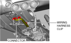
9. Disconnect the connector and wiring harness clip.
10. Place a clean rag behind the engine so that the engine does not contact the rear housing when it is tilted.
11. Remove the front crossmember under cover. (See FRONT CROSSMEMBER UNDER COVER REMOVAL/INSTALLATION.)
12. Disconnect the control rod from the selector lever component. (See AUTOMATIC TRANSMISSION SHIFT MECHANISM REMOVAL/INSTALLATION.)
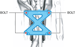
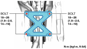
13. Remove the tunnel member.
14. Disconnect the HO2S connector. (See HEATED OXYGEN SENSOR (HO2S) REMOVAL/INSTALLATION [SKYACTIV-G 1.5, SKYACTIV-G 2.0].)
15. Disconnect the TWC from the exhaust manifold (WU-TWC). (See EXHAUST SYSTEM REMOVAL/INSTALLATION [SKYACTIV-G 1.5, SKYACTIV-G 2.0].)
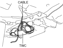
16. Suspend the TWC using a cable as shown in the figure.
17. Remove the power plant frame. (See POWER PLANT FRAME REMOVAL [M66M-D].)
18. Tilt the transmission while being careful not to allow parts on the back of the engine to contact the vehicle body.
19. Clean the outside of the transmission using steam or detergent oil.
20. Drain the ATF. (See AUTOMATIC TRANSMISSION FLUID (ATF) REPLACEMENT [SJ6A-EL].)
21. Remove the electric AT oil pump.
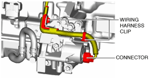
- (1) Disconnect the connector and wiring harness clip.
-
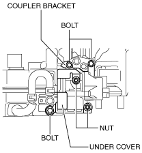
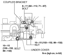
- (2) Remove the under cover.
-
-
Caution
-
• Be careful not to deform the under cover and coupler bracket, if they are deformed the electric AT oil pump may malfunction.
- (3) Remove the coupler bracket.
-
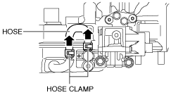
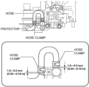
- (4) Slide the hose clamps upward and remove the hose.
-
-
Caution
-
• Because the ATF remaining in the hose may leak, drain the ATF into a container to prevent if from getting on parts.
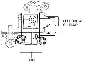
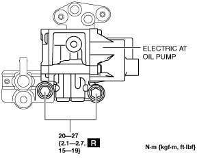
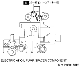
- (5) Remove the electric AT oil pump.
-
-
Caution
-
• Do not use an impact wrench, otherwise damage in the electric oil pump might occur.
• Be careful not to drop the electric AT oil pump. When removing the bolts, support the electric AT oil pump by hand to prevent it from falling.
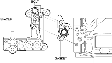
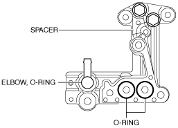
- (6) Remove the spacer and gasket.
-
-
Caution
-
• Do not use an impact wrench, otherwise damage in the electric oil pump might occur.
• Be careful not to drop the spacer. When removing the bolts, support the spacer by hand to prevent it from falling.
-
Note
-
• Remove the spacer and gasket only if they need to be replaced.
• If the spacer is not removed, completely remove any ATF leaked onto and around the spacer to prevent false ATF leakage detection.
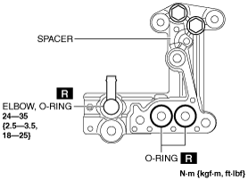
- (7) Remove the elbow and O-rings from the spacer.
-
-
Caution
-
• Be careful not to scratch or damage the elbow pipe coating, otherwise it could cause a malfunction.
22. Clean the contact surfaces of the transmission and spacer.
- (1) Wait until all the ATF drips off of the contact surfaces.
-
- (2) Completely remove any remaining ATF from the contact surfaces.
-
-
Caution
-
• Do not let foreign matter enter the transmission. Otherwise, it could cause a malfunction.
- (3) Verify that there are no cloth threads or foreign matter remaining on the contact surfaces.
-
23. Install the electric AT oil pump to the spacer.
- (1) Completely remove any remaining ATF on the contact surfaces of the electric AT oil pump and spacer, and the area around the installation bolts.
-
-
Caution
-
• Do not let foreign matter enter the electric AT oil pump and spacer. Otherwise, it could cause a malfunction.
- (2) Verify that there are no cloth threads or foreign matter remaining on the contact surfaces.
-
- (3) Install the elbow with a new O-ring assembled to it to the spacer.
-
-
Caution
-
• Install the elbow pipe so that it faces the direction shown in the figure.
• Verify that the coating of the elbow pipe has not peeled off. Replace the elbow if the coating has peeled off.
- (4) Install a new O-ring to the spacer.
-
-
Caution
-
• Verify that the O-ring is aligned correctly.
• Verify that there is no foreign matter on the O-ring.
- (5) Install the electric AT oil pump to the spacer using new bolts.
-
-
Caution
-
• Verify that the O-rings are aligned correctly.
• Do not twist the O-rings.
• Verify that there is no foreign matter on the O-rings.
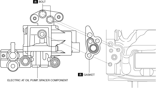
24. Install the electric AT oil pump and spacer component to the transmission.
- (1) Completely remove any remaining ATF on the contact surfaces of the electric AT oil pump, spacer component and transmission, and the area around the installation bolts.
-
-
Caution
-
• Do not let foreign matter enter the electric AT oil pump and spacer. Otherwise, it could cause a malfunction.
- (2) Verify that there are no cloth threads or foreign matter remaining on the contact surfaces.
-
- (3) Verify that the check valve is assembled securely to the transmission.
-
-
• If the check valve is removed from the transmission, assemble it as shown in the figure.
- (4) Put the new bolts through the electric AT oil pump bolt installation holes.
-
-
Caution
-
• Completely remove any oil on the bolts.
- (5) Install a new gasket to the electric AT oil pump and spacer component as shown in the figure.
-
-
Caution
-
• The effectiveness of the seal decreases if the gasket is deformed. Do not drop or apply a shock to the gasket.
• Do not allow foreign matter or ATF to get on the gasket. Remove any foreign matter and ATF on the gasket with a clean cloth.
- (6) Temporarily tighten the bolts while aligning the position of the gasket.
-
-
Caution
-
• Be careful not to scratch or damage the gasket.
- (7) Completely remove any remaining ATF on the electric AT oil pump and bolts.
-
-
• If ATF seeps out after wiping it off, remove the bolts and the electric AT oil pump and completely remove any remaining ATF on the electric AT oil pump again. At this time, replace the gasket and bolts with new ones.
- (8) Verify that there is no ATF on the electric AT oil pump and bolts.
-
-
Caution
-
• Do not tighten the bolts with ATF adhered to the electric AT oil pump and bolts. Otherwise, the bolts may become damaged.
- (9) Tighten the bolts.
-
-
Caution
-
• Do not use an impact wrench, otherwise damage in the electric oil pump might occur.
- (10) Install the hose and hose clamps to the positions shown in the figure.
-
-
Caution
-
• Do not let foreign matter enter the hose and electric AT oil pump. Otherwise, it could cause a malfunction.
• Install the hose clamp tabs so that they face a direction that does not contact the under cover.
• Be careful not to pinch the hose with the protector.
- (11) Completely remove any remaining ATF from the area around the hose.
-
- (12) Install the under cover.
-
-
Caution
-
• Be careful not to deform the under cover and coupler bracket, if they are deformed the electric AT oil pump may malfunction.
- (13) Install the coupler bracket.
-
- (14) Connect the connector and wiring harness clip.
-
25. Install the power plant frame. (See POWER PLANT FRAME INSTALLATION [M66M-D].)
26. Remove the tunnel member temporarily.
27. Connect the TWC to the exhaust manifold (WU-TWC). (See EXHAUST SYSTEM REMOVAL/INSTALLATION [SKYACTIV-G 1.5, SKYACTIV-G 2.0].)
28. Connect the HO2S connector. (See HEATED OXYGEN SENSOR (HO2S) REMOVAL/INSTALLATION [SKYACTIV-G 1.5, SKYACTIV-G 2.0].)
29. Install the tunnel member.
30. Connect the control rod from the selector lever component. (See AUTOMATIC TRANSMISSION SHIFT MECHANISM REMOVAL/INSTALLATION.)
31. Install the front crossmember under cover. (See FRONT CROSSMEMBER UNDER COVER REMOVAL/INSTALLATION.)
32. Connect the connector and wiring harness clip.
33. Install the front console component. (See FRONT CONSOLE REMOVAL/INSTALLATION.)
34. Install the front console panel. (See FRONT CONSOLE PANEL REMOVAL/INSTALLATION.)
35. Install the rear console. (See REAR CONSOLE REMOVAL/INSTALLATION.)
36. Install the parking brake lever boot panel. (See PARKING BRAKE LEVER BOOT PANEL REMOVAL/INSTALLATION.)
37. Install the upper panel. (See UPPER PANEL REMOVAL/INSTALLATION.)
38. Install the shift panel component. (See SHIFT PANEL REMOVAL/INSTALLATION.)
39. Install the selector lever knob. (See AUTOMATIC TRANSMISSION SHIFT MECHANISM REMOVAL/INSTALLATION.)
40. Connect the negative battery terminal. (See NEGATIVE BATTERY TERMINAL DISCONNECTION/CONNECTION.)
41. Add the ATF. (See AUTOMATIC TRANSMISSION FLUID (ATF) REPLACEMENT [SJ6A-EL].)
42. Inspect the ATF level and condition. (See AUTOMATIC TRANSMISSION FLUID (ATF) INSPECTION [SJ6A-EL].) (See AUTOMATIC TRANSMISSION FLUID (ATF) LEVEL ADJUSTMENT [SJ6A-EL].)
43. Bleed the air from the electric AT oil pump.
- (1) Connect the M-MDS to the DLC-2.
-
- (2) After vehicle identification is completed, select the following from the M-MDS initial screen.
-
- 1) “Data logger”
-
- 2) “Module”
-
- 3) “TCM”
-
- (3) Select “EOP” from the PID/DATA Monitor Table.
-
- (4) Perform simulation item “EOP” for 30 s.
-
- (5) Verify that the vehicle does not lurch when the i-stop is operated and the engine restarts.
-
-
• If the vehicle lurches, go back to Step (2) and perform air bleeding again.
-
Caution
-
• When performing simulation item “EOP” successively, wait 10 s or more in between tests. If a 10 s or more wait between tests is not performed, the motor in the electric AT oil pump will overheat, which may cause damage to the electric AT oil pump.
44. Visually verify that ATF does not leak or seep from the transmission.