 |
amxuuw00001245
CONTROL VALVE BODY REMOVAL [SJ6A-EL]
id051311710600
On-Vehicle Removal (Without i-stop)
1. Disconnect the negative battery cable. (See NEGATIVE BATTERY CABLE DISCONNECTION/CONNECTION.)
2. Drain the ATF. (See AUTOMATIC TRANSMISSION FLUID (ATF) REPLACEMENT [SJ6A-EL].)
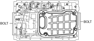
3. Remove the oil pan and the oil pan gasket.
4. Remove the magnets from the oil pan.
amxuuw00001245
|
5. Remove the oil strainer from the control valve body component.
amxuuw00003553
|
6. Remove the O-ring from the oil strainer.
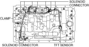
7. Disconnect the connectors from the solenoids.
amxuuw00003554
|
8. Disconnect the coupler component from the clamps.
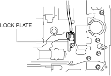
9. Remove the lock plate from the control valve body component.
amxuuw00003555
|
10. Pull the TFT sensor from the control valve body component.
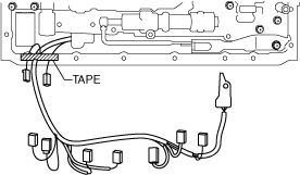
11. Fix the coupler component with tape to the transmission case as shown in the figure.
amxuuw00003556
|
12. Remove the detent spring cover and detent spring from the control valve body component.
amxuuw00003557
|
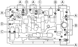
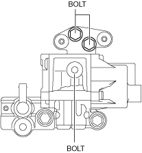
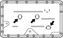
13. Remove the bolts from the transmission case as shown in the figure.
ardjjw00005151
|
14. Disconnect the manual valve link and remove the control valve body component.
amxuuw00003558
|
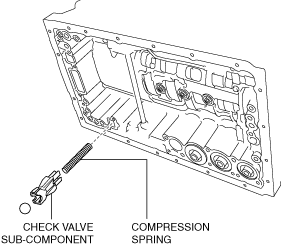
15. Remove the check valve sub-component and the compression spring from the transmission case.
amxzzw00004503
|
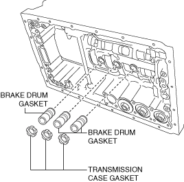
16. Remove the transmission case gaskets and the brake drum gaskets from the transmission case.
amxzzw00004504
|
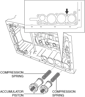
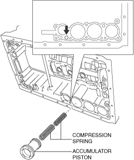
17. Apply compressed air into the oil passage as shown in the figure and remove the accumulator pistons (C-2, B-3) and the compression springs from the transmission case.
amxzzw00004505
|
18. Remove the snap rings from the accumulator pistons (C-2, B-3) using a flathead screwdriver.
19. Remove the compression springs from the accumulator pistons (C-2, B-3).
20. Remove the O-rings from the accumulator pistons (C-2, B-3) using a flathead screwdriver.
21. Apply compressed air into the oil passage as shown in the figure and remove the accumulator piston (C-3) and compression springs from the transmission case.
amxzzw00004506
|
22. Remove the O-rings from the accumulator piston (C-3) using a flathead screwdriver.
23. Remove the accumulator valve and compression springs from the transmission case.
amxzzw00004507
|
On-Vehicle Removal (With i-stop)
1. Disconnect the negative battery cable. (See NEGATIVE BATTERY CABLE DISCONNECTION/CONNECTION.)
2. Remove the selector lever knob. (See AUTOMATIC TRANSMISSION SHIFT MECHANISM REMOVAL/INSTALLATION.)
3. Remove the shift panel component. (See SHIFT PANEL REMOVAL/INSTALLATION.)
4. Remove the upper panel. (See UPPER PANEL REMOVAL/INSTALLATION.)
5. Remove the parking brake lever boot panel. (See PARKING BRAKE LEVER BOOT PANEL REMOVAL/INSTALLATION.)
6. Remove the rear console. (See REAR CONSOLE REMOVAL/INSTALLATION.)
7. Remove the front console panel. (See FRONT CONSOLE PANEL REMOVAL/INSTALLATION.)
8. Remove the front console component. (See FRONT CONSOLE REMOVAL/INSTALLATION.)
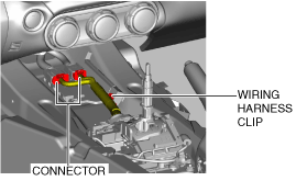
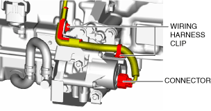
9. Disconnect the connector and wiring harness clip.
amxuuw00002845
|
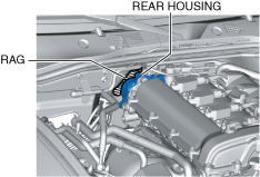
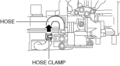
10. Place a clean rag behind the engine so that the engine does not contact the rear housing when it is tilted.
amxuuw00004812
|
11. Remove the front crossmember under cover. (See FRONT CROSSMEMBER UNDER COVER REMOVAL/INSTALLATION.)
12. Disconnect the control rod from the selector lever component. (See AUTOMATIC TRANSMISSION SHIFT MECHANISM REMOVAL/INSTALLATION.)
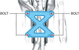
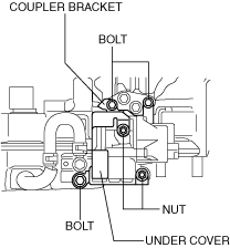
13. Remove the tunnel member.
amxuuw00003817
|
14. Disconnect the HO2S connector. (See HEATED OXYGEN SENSOR (HO2S) REMOVAL/INSTALLATION [SKYACTIV-G 1.5, SKYACTIV-G 2.0].)
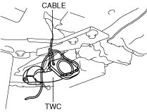
15. Disconnect the TWC from the exhaust manifold (WU-TWC). (See EXHAUST SYSTEM REMOVAL/INSTALLATION [SKYACTIV-G 1.5, SKYACTIV-G 2.0].)
16. Suspend the TWC using a cable as shown in the figure.
amxuuw00002847
|
17. Remove the power plant frame. (See POWER PLANT FRAME REMOVAL [M66M-D].)
18. Tilt the transmission while being careful not to allow parts on the back of the engine to contact the vehicle body.
19. Clean the outside of the transmission using steam or detergent oil.
20. Drain the ATF. (See AUTOMATIC TRANSMISSION FLUID (ATF) REPLACEMENT [SJ6A-EL].)
21. Remove the electric AT oil pump.
amxzzw00003295
|
amxzzw00003296
|
amxzzw00003308
|
amxzzw00005876
|
22. Remove the oil pan and the oil pan gasket.
23. Remove the magnets from the oil pan.
amxuuw00001245
|
24. Remove the oil strainer from the control valve body component.
amxuuw00003553
|
25. Remove the O-ring from the oil strainer.
26. Disconnect the connectors from the solenoids.
amxuuw00003554
|
27. Disconnect the coupler component from the clamps.
28. Remove the lock plate from the control valve body component.
amxuuw00003555
|
29. Pull the TFT sensor from the control valve body component.
30. Fix the coupler component with tape to the transmission case as shown in the figure.
amxuuw00003556
|
31. Remove the detent spring cover and detent spring from the control valve body component.
amxuuw00003557
|
32. Remove the bolts from the transmission case as shown in the figure.
ardjjw00005151
|
33. Disconnect the manual valve link and remove the control valve body component.
amxuuw00003558
|
34. Remove the check valve sub-component and the compression spring from the transmission case.
amxzzw00004503
|
35. Remove the transmission case gaskets and the brake drum gaskets from the transmission case.
amxzzw00004504
|
36. Apply compressed air into the oil passage as shown in the figure and remove the accumulator pistons (C-2, B-3) and the compression springs from the transmission case.
amxzzw00004505
|
37. Remove the snap rings from the accumulator pistons (C-2, B-3) using a flathead screwdriver.
38. Remove the compression springs from the accumulator pistons (C-2, B-3).
39. Remove the O-rings from the accumulator pistons (C-2, B-3) using a flathead screwdriver.
40. Apply compressed air into the oil passage as shown in the figure and remove the accumulator piston (C-3) and compression springs from the transmission case.
amxzzw00004506
|
41. Remove the O-rings from the accumulator piston (C-3) using a flathead screwdriver.
42. Remove the accumulator valve and compression springs from the transmission case.
amxzzw00004507
|