 |
amxzzw00004473
CONTROL VALVE BODY INSTALLATION [SJ6A-EL]
id051311710700
On-Vehicle Installation (Without i-stop)
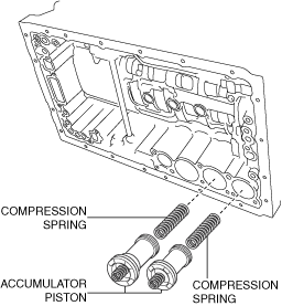
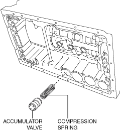
1. Install the accumulator valve and compression springs to the transmission case.
amxzzw00004473
|
2. Coat the new O-rings with ATF, and install it to the accumulator piston (C-3).
3. Install the accumulator piston (C-3) and the compression spring to the transmission case.
amxzzw00004474
|
4. Coat the new O-rings with ATF, and install it to the accumulator pistons (C-2, B-3).
5. Install the compression springs and the snap rings to the accumulator pistons (C-2, B-3) using a flathead screwdriver.
6. Install the accumulator pistons (C-2, B-3) and the compression springs to the transmission case.
amxzzw00004475
|
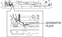
7. Coat the new transmission gaskets and the new brake drum gaskets with ATF, and install them to the transmission case.
amxzzw00004476
|
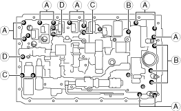
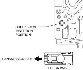
8. Install the check valve sub-component and the compression spring to the transmission case.
amxzzw00004477
|
9. Connect the manual valve link and install the control valve body component.
amxuuw00003558
|
amxuuw00003567
|
10. Temporarily install the control valve body component with the bolts.
ardjjw00005151
|
11. Tighten the bolts.
12. Install the detent spring cover and detent spring with the bolt to the control valve body component.
amxuuw00003557
|
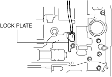
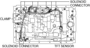
13. Install the TFT sensor and the lock plate with the bolt to the control valve body component.
amxuuw00003555
|
14. Connect the coupler component to the clamps.
amxuuw00003554
|
15. Connect the connectors to the solenoids.
16. Coat a new O-ring with ATF and install it to the oil strainer.
17. Install the oil strainer with the bolts to the control valve body component.
amxuuw00003553
|
18. Clean the contact surface of oil pan and transmission case.
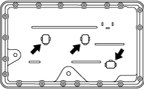
19. Install the magnets to the oil pan.
amxuuw00000470
|
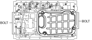
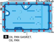
20. Install a new oil pan gasket and the oil pan to the transmission case.
amxuuw00003569
|
21. Install the bolts to the transmission case.
22. Connect the negative battery cable. (See NEGATIVE BATTERY CABLE DISCONNECTION/CONNECTION.)
23. Add ATF and, with the engine idling, inspect the ATF level and for leakage. (See AUTOMATIC TRANSMISSION FLUID (ATF) LEVEL ADJUSTMENT [SJ6A-EL].)
24. Perform the mechanical system test. (See MECHANICAL SYSTEM TEST [SJ6A-EL].)
25. Perform the road test. (See ROAD TEST [SJ6A-EL].)
On-Vehicle Installation (With i-stop)
1. Install the accumulator valve and compression springs to the transmission case.
amxzzw00004473
|
2. Coat the new O-rings with ATF, and install it to the accumulator piston (C-3).
3. Install the accumulator piston (C-3) and the compression spring to the transmission case.
amxzzw00004474
|
4. Coat the new O-rings with ATF, and install it to the accumulator pistons (C-2, B-3).
5. Install the compression springs and the snap rings to the accumulator pistons (C-2, B-3) using a flathead screwdriver.
6. Install the accumulator pistons (C-2, B-3) and the compression springs to the transmission case.
amxzzw00004475
|
7. Coat the new transmission gaskets and the new brake drum gaskets with ATF, and install them to the transmission case.
amxzzw00004476
|
8. Install the check valve sub-component and the compression spring to the transmission case.
amxzzw00004477
|
9. Connect the manual valve link and install the control valve body component.
amxuuw00003558
|
amxuuw00003567
|
10. Temporarily install the control valve body component with the bolts.
ardjjw00005151
|
11. Tighten the bolts.
12. Install the detent spring cover and detent spring with the bolt to the control valve body component.
amxuuw00003557
|
13. Install the TFT sensor and the lock plate with the bolt to the control valve body component.
amxuuw00003555
|
14. Connect the coupler component to the clamps.
amxuuw00003554
|
15. Connect the connectors to the solenoids.
16. Coat a new O-ring with ATF and install it to the oil strainer.
17. Install the oil strainer with the bolts to the control valve body component.
amxuuw00003553
|
18. Clean the contact surface of oil pan and transmission case.
19. Install the magnets to the oil pan.
amxuuw00000470
|
20. Install a new oil pan gasket and the oil pan to the transmission case.
amxuuw00003569
|
21. Install the bolts to the transmission case.
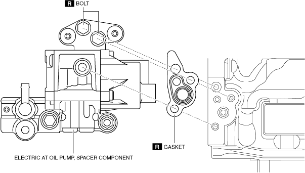
22. Clean the contact surfaces of the transmission and spacer.
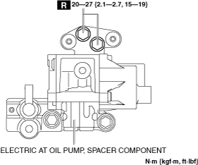
23. Install the electric AT oil pump and spacer component to the transmission.
amxzzw00003303
|
amxzzw00004457
|
amxzzw00003305
|
amxzzw00003314
|
amxzzw00003307
|
amxzzw00003295
|
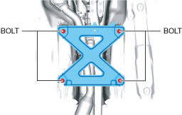
24. Install the power plant frame. (See POWER PLANT FRAME INSTALLATION [M66M-D].)
25. Remove the tunnel member temporarily.
amxuuw00003817
|
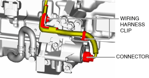
26. Connect the TWC to the exhaust manifold (WU-TWC). (See EXHAUST SYSTEM REMOVAL/INSTALLATION [SKYACTIV-G 1.5, SKYACTIV-G 2.0].)
27. Connect the HO2S connector. (See HEATED OXYGEN SENSOR (HO2S) REMOVAL/INSTALLATION [SKYACTIV-G 1.5, SKYACTIV-G 2.0].)
28. Install the tunnel member.
amxuuw00003818
|
29. Connect the control rod from the selector lever component. (See AUTOMATIC TRANSMISSION SHIFT MECHANISM REMOVAL/INSTALLATION.)
30. Install the front crossmember under cover. (See FRONT CROSSMEMBER UNDER COVER REMOVAL/INSTALLATION.)
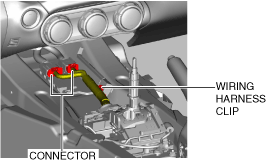
31. Connect the connector and wiring harness clip.
amxuuw00002845
|
32. Install the front console component. (See FRONT CONSOLE REMOVAL/INSTALLATION.)
33. Install the front console panel. (See FRONT CONSOLE PANEL REMOVAL/INSTALLATION.)
34. Install the rear console. (See REAR CONSOLE REMOVAL/INSTALLATION.)
35. Install the parking brake lever boot panel. (See PARKING BRAKE LEVER BOOT PANEL REMOVAL/INSTALLATION.)
36. Install the upper panel. (See UPPER PANEL REMOVAL/INSTALLATION.)
37. Install the shift panel component. (See SHIFT PANEL REMOVAL/INSTALLATION.)
38. Install the selector lever knob. (See AUTOMATIC TRANSMISSION SHIFT MECHANISM REMOVAL/INSTALLATION.)
39. Connect the negative battery cable. (See NEGATIVE BATTERY CABLE DISCONNECTION/CONNECTION.)
40. Add the ATF. (See AUTOMATIC TRANSMISSION FLUID (ATF) REPLACEMENT [SJ6A-EL].)
41. Inspect the ATF level and condition. (See AUTOMATIC TRANSMISSION FLUID (ATF) INSPECTION [SJ6A-EL].) (See AUTOMATIC TRANSMISSION FLUID (ATF) LEVEL ADJUSTMENT [SJ6A-EL].)
42. Bleed the air from the electric AT oil pump.
43. Perform the mechanical system test. (See MECHANICAL SYSTEM TEST [SJ6A-EL].)
44. Perform the road test. (See ROAD TEST [SJ6A-EL].)