STEERING WHEEL AND COLUMN REMOVAL/INSTALLATION
id061300801400
-
Warning
-
1. Disconnect the negative battery cable and wait for 1 min or more. (See NEGATIVE BATTERY CABLE DISCONNECTION/CONNECTION. )
2. Remove the driver-side air bag module. (See DRIVER-SIDE AIR BAG MODULE REMOVAL.) (See DRIVER-SIDE AIR BAG MODULE INSTALLATION.)
3. Straighten the steering wheel.
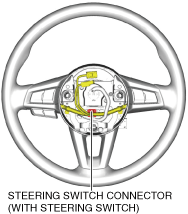
4. Disconnect the steering switch connector. (With steering switch)
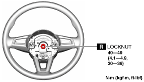
5. Remove the locknut.
6. Remove the steering wheel using any commercially available puller.
-
Caution
-
• Do not try to remove the steering wheel by hitting the shaft with a hammer. The steering column will be damaged.
7. Remove the following parts:
- (1) Selector lever knob (AT vehicles) (See AUTOMATIC TRANSMISSION SHIFT MECHANISM REMOVAL/INSTALLATION.)
-
- (2) Shift lever knob (MT vehicles) (See TRANSMISSION REMOVAL/INSTALLATION [M66M-D].)
-
- (3) Shift panel component (See SHIFT PANEL REMOVAL/INSTALLATION.)
-
- (4) Upper panel (See UPPER PANEL REMOVAL/INSTALLATION.)
-
- (5) Parking brake lever boot panel (See PARKING BRAKE LEVER BOOT PANEL REMOVAL/INSTALLATION.)
-
- (6) Rear console (See REAR CONSOLE REMOVAL/INSTALLATION.)
-
- (7) Front console panel (See FRONT CONSOLE PANEL REMOVAL/INSTALLATION.)
-
- (8) Front console component (See FRONT CONSOLE REMOVAL/INSTALLATION.)
-
- (9) Driver-side scuff plate (See SCUFF PLATE REMOVAL/INSTALLATION.)
-
- (10) Driver-side front side trim (See FRONT SIDE TRIM REMOVAL/INSTALLATION.)
-
- (11) Driver-side A-pillar trim (See A-PILLAR TRIM REMOVAL/INSTALLATION.)
-
- (12) Bonnet release lever (See BONNET RELEASE LEVER AND RELEASE CABLE REMOVAL/INSTALLATION.)
-
- (13) Driver-side lower panel (See DRIVER-SIDE LOWER PANEL REMOVAL/INSTALLATION.)
-
- (14) Passenger-side scuff plate (See SCUFF PLATE REMOVAL/INSTALLATION.)
-
- (15) Passenger-side front side trim (See FRONT SIDE TRIM REMOVAL/INSTALLATION.)
-
- (16) Passenger-side A-pillar trim (See A-PILLAR TRIM REMOVAL/INSTALLATION.)
-
- (17) Passenger-side lower panel (See PASSENGER-SIDE LOWER PANEL REMOVAL/INSTALLATION.)
-
- (18) Center panel No.2 (See CENTER PANEL No.2 REMOVAL/INSTALLATION.)
-
- (19) Column cover (See COLUMN COVER REMOVAL/INSTALLATION.)
-
- (20) Meter hood (See METER HOOD REMOVAL/INSTALLATION.)
-
- (21) Instrument cluster (See INSTRUMENT CLUSTER REMOVAL/INSTALLATION.)
-
- (22) Clock spring (See CLOCK SPRING REMOVAL/INSTALLATION.)
-
- (23) Light switch (See LIGHT SWITCH REMOVAL/INSTALLATION.)
-
- (24) Wiper and washer switch (See WIPER AND WASHER SWITCH REMOVAL/INSTALLATION.)
-
- (25) Start stop unit (See START STOP UNIT REMOVAL/INSTALLATION.)
-
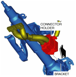
8. Disconnect the connector holder from the bracket of the steering column.
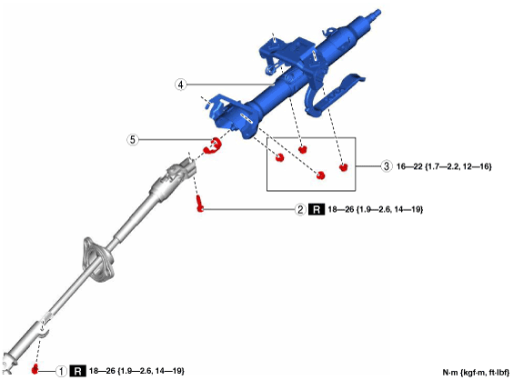
9. Remove in the order indicated in the table.
10. Install in the reverse order of removal.
|
1
|
Joint bolt A
|
|
2
|
Joint bolt B
|
|
3
|
Nut
|
|
4
|
Steering Column
|
|
5
|
Clip
|
Steering Column Removal Note
-
Caution
-
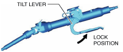
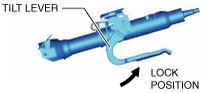
• Always lock the tilt lever to prevent damage to the steering column. In addition, do not unlock the tilt lever until the steering column installation is completed.
• If the steering column is removed, remove it according to the procedure to prevent damage to intermediate shaft that could result if the steering column is removed in the incorrect order.
1. Lock the tilt lever.
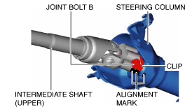
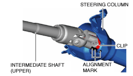
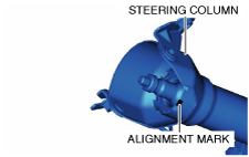
2. Place alignment marks on the steering column, clip, and intermediate shaft (upper) as shown in the figure.
3. Remove the joint bolt B.
4. Disconnect the intermediate shaft (upper) from the steering column.
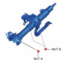
5. Remove the nuts, then remove the steering column from the dashboard member.
6. Remove the clip from the steering column.
Steering Column Installation Note
-
Caution
-
• Always lock the tilt lever to prevent damage to the steering column. In addition, do not unlock the tilt lever until the steering column installation is completed.
• If the steering column is installed, install it according to the procedure to prevent damage to intermediate shaft that could result if the steering column is installed in the incorrect order.
1. Verify that the tilt lever of the steering column is locked.
2. Install the clip to the steering column.
3. Temporarily install the steering column to the dashboard member using nuts A and B.
4. Tighten the nuts in the order of nut A and nut B.
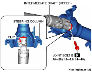
5. Install the intermediate shaft (upper) with the alignment marks on the intermediate shaft (upper) and the clip, which were marked before removing the steering column, aligned.
-
Note
-
• When replacing the steering column with a new one, place an alignment mark on the new part in the same position as the removed steering column.
6. Verify that the semicircular shape of the clip and U-shape groove of the steering column matches and joint bolt B can be inserted.
7. Install the joint bolt B.