|
1
|
INSPECT SEAT CUSHION
• Inspect the seat cushion.
• Is the seat cushion damp?
|
Yes
|
Dry the seat cushion, then go to next step.
|
|
No
|
Go to the next step.
|
|
2
|
INSPECT BATTERY
• Inspect the battery terminals for looseness.
• Is there any malfunction?
|
Yes
|
Connect the battery terminals securely, and recharge or replace the battery.
Then go to the next step.
|
|
No
|
Go to the next step.
|
|
3
|
PERFORM OCCUPANT CLASSIFICATION SENSOR CALIBRATION
• Perform the occupant classification sensor calibration.
• Clear DTCs using the M-MDS.
• Verify DTCs using the M-MDS.
• Is DTC B00A0:09 displayed?
|
Yes
|
Go to the next step.
|
|
No
|
DTC troubleshooting completed.
|
|
4
|
INSPECT OCCUPANT CLASSIFICATION SENSOR CONNECTOR
• Switch the ignition off.
• Disconnect the negative battery cable and wait for 1 min.
• Disconnect the occupant classification sensor connector.
• Inspect the occupant classification sensor connector. (Corrosion, damage, and disconnected pins).
• Is there any malfunction of the occupant classification sensor connector?
|
Yes
|
Repair or replace the malfunctioning part, then go to Step 17.
|
|
No
|
Go to the next step.
|
|
5
|
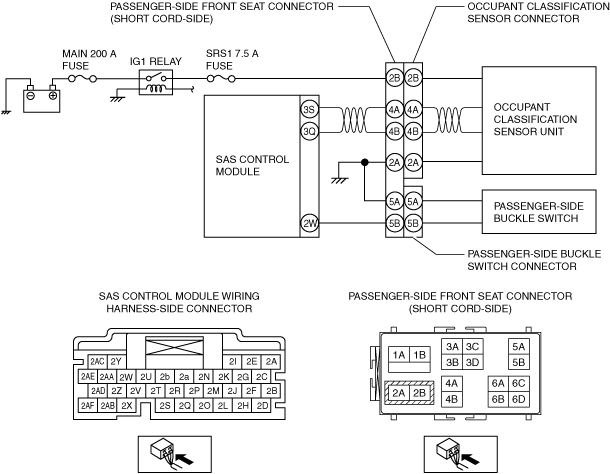
INSPECT OCCUPANT CLASSIFICATION SENSOR GROUND CIRCUIT FOR OPEN CIRCUIT
• Occupant classification sensor connector is disconnected.
• Inspect for continuity between the following terminal and body ground.
-
― Passenger-side front seat connector (short cord-side) terminal 2A
-
Note
-
• Inspect for continuity while shaking the wiring harness between the passenger-side front seat connector and body ground.
• Is there continuity?
|
Yes
|
Go to the next step.
|
|
No
|
Refer to the wiring diagram and verify whether or not there is a common connector between passenger-side front seat connector terminal and body ground.
If there is a common connector:
• Determine the malfunctioning part by inspecting the common connector and the terminal for corrosion, damage, or pin disconnection, and the common wiring harness for an open circuit.
• Replace the malfunctioning part.
If there is no common connector:
• Replace the wiring harness which has an open circuit.
Go to Step 17.
|
|
6
|
INSPECT OCCUPANT CLASSIFICATION SENSOR GROUND CIRCUIT FOR SHORT TO POWER SUPPLY
• Occupant classification sensor connector is disconnected.
• Connect the negative battery cable.
• Switch the ignition ON (engine off or on).
• Measure the voltage at the following terminal:
-
― Passenger-side front seat connector (short cord-side) terminal 2A
-
Note
-
• Measure the voltage while shaking the wiring harness between the passenger-side front seat connector and body ground.
• Is the voltage 0 V?
|
Yes
|
Go to the next step.
|
|
No
|
Refer to the wiring diagram and verify whether or not there is a common connector between passenger-side front seat connector terminal and body ground.
If there is a common connector:
• Determine the malfunctioning part by inspecting the common connector and the terminal for corrosion, damage, or pin disconnection, and the common wiring harness for a short to power supply.
• Replace the malfunctioning part.
If there is no common connector:
• Replace the wiring harness which has a short to power supply.
Go to Step 17.
|
|
7
|
INSPECT OCCUPANT CLASSIFICATION SENSOR POWER SUPPLY CIRCUIT
• Occupant classification sensor connector is disconnected.
• Measure the voltage at the following terminal:
-
― Passenger-side front seat connector (short cord-side) terminal 2B
-
Note
-
• Measure the voltage while shaking the wiring harness between the passenger-side front seat connector and IG1 relay.
• Is the voltage B+?
|
Yes
|
Go to the next step.
|
|
No
|
Refer to the wiring diagram and verify whether or not there is a common connector between passenger-side front seat connector terminal and IG1 relay.
If there is a common connector:
• Determine the malfunctioning part by inspecting the common connector and the terminal for corrosion, damage, or pin disconnection, and the common wiring harness.
• Replace the malfunctioning part.
If there is no common connector:
• Replace the wiring harness.
Go to Step 17.
|
|
8
|
INSPECT PASSENGER-SIDE BUCKLE SWITCH OPERATION
• Inspect the passenger-side buckle switch operation.
• Does the passenger-side buckle switch operate normally?
|
Yes
|
Go to Step 15.
|
|
No
|
Go to the next step.
|
|
9
|
INSPECT PASSENGER-SIDE BUCKLE SWITCH
• Switch the ignition off.
• Disconnect the negative battery cable and wait for 1 min.
• Inspect the passenger-side buckle switch.
• Is the passenger-side buckle switch normal?
|
Yes
|
Go to the next step.
|
|
No
|
Replace the passenger-side buckle switch.
Then go to Step 17.
|
|
10
|
INSPECT PASSENGER-SIDE BUCKLE SWITCH GROUND CIRCUIT FOR OPEN CIRCUIT
• Passenger-side buckle switch connector is disconnected.
• Inspect for continuity between the following terminal and body ground:
-
― Passenger-side front seat connector (short cord-side) terminal 5A
-
Note
-
• Inspect for continuity while shaking the wiring harness between the passenger-side front seat connector and body ground.
• Is there continuity?
|
Yes
|
Go to the next step.
|
|
No
|
Refer to the wiring diagram and verify whether or not there is a common connector between passenger-side front seat connector terminal and body ground.
If there is a common connector:
• Determine the malfunctioning part by inspecting the common connector and the terminal for corrosion, damage, or pin disconnection, and the common wiring harness for an open circuit.
• Replace the malfunctioning part.
If there is no common connector:
• Replace the wiring harness which has an open circuit.
Go to Step 17.
|
|
11
|
INSPECT PASSENGER-SIDE BUCKLE SWITCH GROUND CIRCUIT FOR SHORT TO POWER SUPPLY
• Passenger-side buckle switch connector is disconnected.
• Connect the negative battery cable.
• Switch the ignition ON (engine off or on).
• Measure the voltage at the following terminal:
-
― Passenger-side front seat connector (short cord-side) terminal 5A
-
Note
-
• Measure the voltage while shaking the wiring harness between the passenger-side front seat connector and body ground.
• Is the voltage 0 V?
|
Yes
|
Go to the next step.
|
|
No
|
Refer to the wiring diagram and verify whether or not there is a common connector between passenger-side front seat connector terminal and body ground.
If there is a common connector:
• Determine the malfunctioning part by inspecting the common connector and the terminal for corrosion, damage, or pin disconnection, and the common wiring harness for a short to power supply.
• Replace the malfunctioning part.
If there is no common connector:
• Replace the wiring harness which has a short to power supply.
Go to Step 17.
|
|
12
|
INSPECT PASSENGER-SIDE BUCKLE SWITCH SIGNAL CIRCUIT FOR SHORT TO GROUND
• Passenger-side buckle switch connector is disconnected.
• Switch the ignition off.
• Disconnect the negative battery cable and wait for 1 min.
• Disconnect the driver and passenger-side pre-tensioner seat belt connectors.
• Inspect for continuity between the following terminals and body ground:
-
― Passenger-side front seat connector (short cord-side) terminal 5B
-
Note
-
• Inspect for continuity while shaking the wiring harness between the SAS control module and passenger-side front seat connector.
• Is there continuity?
|
Yes
|
Go to the next step.
|
|
No
|
Refer to the wiring diagram and verify whether or not there is a common connector between passenger-side front seat connector terminal and SAS control module terminal.
If there is a common connector:
• Determine the malfunctioning part by inspecting the common connector and the terminal for corrosion, damage, or pin disconnection, and the common wiring harness for a short to ground.
• Replace the malfunctioning part.
If there is no common connector:
• Replace the wiring harness which has a short to ground.
Go to Step 17.
|
|
13
|
INSPECT PASSENGER-SIDE BUCKLE SWITCH SIGNAL CIRCUIT FOR OPEN CIRCUIT
• Passenger-side buckle switch and SAS control module connectors are disconnected.
• Inspect for continuity between the following terminal:
-
― Passenger-side front seat connector (short cord-side) terminal 5B—SAS control module terminal 2W
-
Note
-
• Inspect for continuity while shaking the wiring harness between the SAS control module and passenger-side front seat connector.
• Is there continuity?
|
Yes
|
Refer to the wiring diagram and verify whether or not there is a common connector between passenger-side front seat connector terminal and SAS control module terminal.
If there is a common connector:
• Determine the malfunctioning part by inspecting the common connector and the terminal for corrosion, damage, or pin disconnection, and the common wiring harness for an open circuit.
• Replace the malfunctioning part.
If there is no common connector:
• Replace the wiring harness which has an open circuit.
Go to Step 17.
|
|
No
|
Go to the next step.
|
|
14
|
INSPECT PASSENGER-SIDE BUCKLE SWITCH SIGNAL CIRCUIT FOR SHORT TO POWER SUPPLY
• Passenger-side buckle switch and SAS control module connectors are disconnected.
• Measure the voltage at the following terminal:
-
― Passenger-side front seat connector (short cord-side) terminal 5B
-
Note
-
• Measure the voltage while shaking the wiring harness between the SAS control module and passenger-side front seat connector.
• Is the voltage 0 V?
|
Yes
|
Repair the passenger-side buckle switch connector. (Corrosion, damage, and disconnected pins)
Go to Step 17.
|
|
No
|
Refer to the wiring diagram and verify whether or not there is a common connector between passenger-side front seat connector terminal and SAS control module terminal.
If there is a common connector:
• Determine the malfunctioning part by inspecting the common connector and the terminal for corrosion, damage, or pin disconnection, and the common wiring harness for a short to power supply.
• Replace the malfunctioning part.
If there is no common connector:
• Replace the wiring harness which has a short to power supply.
Go to Step 17.
|
|
15
|
INSPECT PASSENGER-SIDE SEAT WARMER OPERATION
• Inspect the passenger-side seat warmer operation.
• Does the passenger-side seat warmer operate normally?
|
Yes
|
Go to the next step.
|
|
No
|
• Inspect the passenger-side seat warmer unit connector. (Corrosion, damage, and disconnected pins)
• Inspect the passenger-side seat warmer unit.
• Refer to the wiring diagram and inspect the passenger-side seat warmer unit body ground circuit.
• Refer to the wiring diagram and inspect the wiring harness between the seat warmer control unit and passenger-side seat warmer unit.
Repair or replace the malfunctioning part, then go to Step 17.
|
|
16
|
INSPECT PASSENGER-SIDE HEADREST SPEAKER OPERATION
• Inspect the passenger-side headrest speaker operation.
• Does the passenger-side headrest speaker operate normally?
|
Yes
|
Go to the next step.
|
|
No
|
• Inspect the passenger-side headrest speaker connector. (Corrosion, damage, and disconnected pins)
• Inspect the passenger-side headrest speaker.
• Refer to the wiring diagram and inspect the passenger-side headrest speaker circuit.
Repair or replace the malfunctioning part, then go to the next step.
|
|
17
|
PERFORM DTC INSPECTION
• Perform the occupant classification sensor calibration.
• Clear DTCs using the M-MDS.
• Verify DTCs using the M-MDS.
• Is DTC B00A0:09 displayed?
|
Yes
|
Replace the occupant classification sensor.
Then go to the next step.
|
|
No
|
DTC troubleshooting completed.
|
|
18
|
PERFORM SAS CONTROL MODULE DTC INSPECTION
• Clear the DTC for the SAS control module using the M-MDS.
• Perform the DTC inspection for the SAS control module using the M-MDS.
• Is the same DTC present?
|
Yes
|
Replace the SAS control module.
|
|
No
|
DTC troubleshooting completed.
|