NO SOUND OUTPUT IN ALL MODES [ENTERTAINMENT SYSTEM [WITH CENTER DISPLAY]]


id0903l8060500


Without Bose®

Description
NO SOUND OUTPUT IN ALL MODES
Sound is not output from speakers even if any mode is selected
Possible Causes
•  Connector poor contact or terminal damage
•  Tuner and amp unit (TAU) ACC power supply circuit malfunction
―  Short to ground in wiring harness between battery and TAU terminal 2R*1/ 2F*2
―  Open circuit in wiring harness between battery and TAU terminal 2R*1/ 2F*2
―  MAIN 200A fuse malfunction
―  IG2 30A fuse malfunction
―  RADIO 7.5A fuse malfunction
―  ACC relay malfunction
•  Open circuit in wiring harness between TAU terminal 2W*1/ 2A*2 and body ground
•  Speaker malfunction
―  Malfunction of the following speakers.
•  Door speaker (LH)
•  Door speaker (RH)
•  Tweeter (LH)
•  Tweeter (RH)
•  Headrest speaker (LH)
•  Headrest speaker (RH)
―  Open circuit or short to ground in wiring harness between the following terminals:
L.H.D.
•  TAU terminal 2A*1/ 2P*2 and door speaker (LH) terminal C
•  TAU terminal 2C*1/ 2N*2 and door speaker (LH) terminal B
•  TAU terminal 2D*1/ 2Q*2 and door speaker (RH) terminal C
•  TAU terminal 2F*1/ 2O*2 and door speaker (RH) terminal B
•  TAU terminal 2A*1/ 2P*2 and tweeter (LH) terminal B
•  TAU terminal 2C*1/ 2N*2 and tweeter (LH) terminal A
•  TAU terminal 2D*1/ 2Q*2 and tweeter (RH) terminal B
•  TAU terminal 2F*1/ 2O*2 and tweeter (RH) terminal A
•  TAU terminal 2V*1/ 2M*2 and headrest speaker (LH) terminal B
•  TAU terminal 2X*1/ 2K*2 and headrest speaker (LH) terminal A
•  TAU terminal 2S*1/ 2L*2 and headrest speaker (RH) terminal B
•  TAU terminal 2U*1/ 2J*2 and headrest speaker (RH) terminal A
R.H.D.
•  TAU terminal 2A*1/ 2P*2 and door speaker (LH) terminal C
•  TAU terminal 2C*1/ 2N*2 and door speaker (LH) terminal B
•  TAU terminal 2D*1/ 2Q*2 and door speaker (RH) terminal C
•  TAU terminal 2F*1/ 2O*2 and door speaker (RH) terminal B
•  TAU terminal 2A*1/ 2P*2 and tweeter (LH) terminal B
•  TAU terminal 2C*1/ 2N*2 and tweeter (LH) terminal A
•  TAU terminal 2D*1/ 2Q*2 and tweeter (RH) terminal B
•  TAU terminal 2F*1/ 2O*2 and tweeter (RH) terminal A
•  TAU terminal 2S*1/ 2L*2 and headrest speaker (LH) terminal B
•  TAU terminal 2U*1/ 2J*2 and headrest speaker (LH) terminal A
•  TAU terminal 2V*1/ 2M*2 and headrest speaker (RH) terminal B
•  TAU terminal 2X*1/ 2K*2 and headrest speaker (RH) terminal A
•  TAU malfunction
•  Connectivity master unit (CMU) malfunction
System Wiring Diagram

*1  :TAU connector 24-pin type
*2  :TAU connector 20-pin type

Diagnostic Procedure

Step

Inspection

Action

1
VERIFY MALFUNCTION SYMPTOM
•  Switch the ignition to ACC or ON (engine off or on).
•  Launch the on-board diagnostic assist function.
•  Select assist code “94”.
•  Press the [ENTER] and verify that the sound is output from each speaker.
•  Is sound output from each speaker in the order?
Yes
•  System is normal.
•  Due to the possibility that sound is not output in some modes, verify the malfunction in the symptom troubleshooting chart and perform the other applicable malfunction diagnosis.
No
•  No sound is produced from all speakers
―  Go to the next step.
•  No sound is produced from some speakers
―  Go to Step 7.
2
INSPECT TAU CONNECTOR
•  Switch the ignition off.
•  Disconnect the negative battery cable.
•  Disconnect the TAU connector.
•  Inspect the connector engagement and connection condition and inspect the terminals for damage, deformation, corrosion, or disconnection.
•  Is the connector normal?
Yes
Go to the next step.
No
Repair or replace the connector, then go to Step 12.
3
INSPECT CMU CONNECTOR
•  Disconnect the CMU connector.
•  Inspect the connector engagement and connection condition and inspect the terminals for damage, deformation, corrosion, or disconnection.
•  Is the connector normal?
Yes
Go to the next step.
No
Repair or replace the connector, then go to Step 12.
4
INSPECT TAU ACC POWER SUPPLY VOLTAGE
•  Verify that the TAU connector is disconnected.
•  Reconnect the negative battery cable.
•  Switch the ignition to ACC or ON (engine off or on).
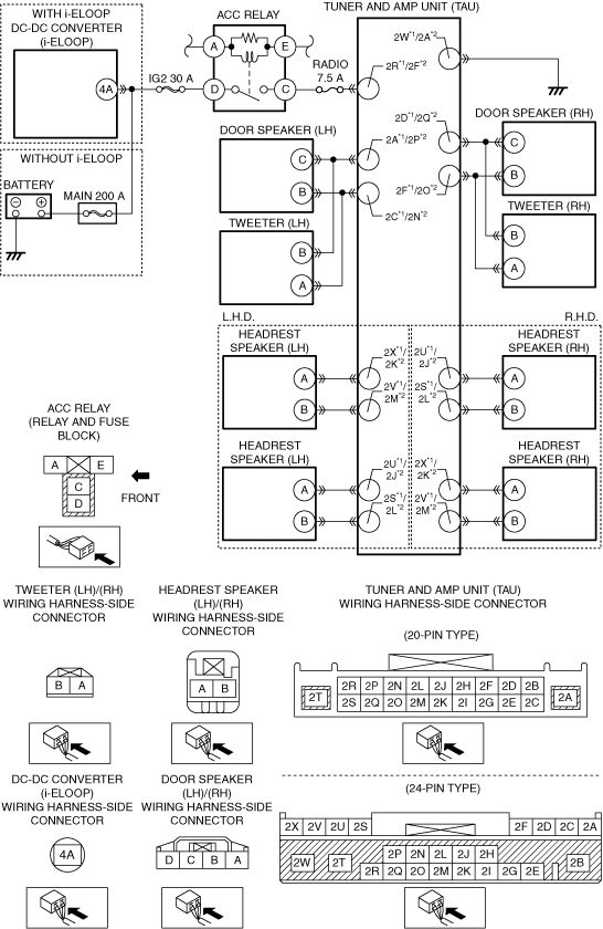
•  Measure the voltage at TAU terminal 2R*1/ 2F*2 (vehicle wiring harness side).
•  Is the voltage B+?
Yes
Go to the next step.
No
Inspect the MAIN 200A fuse, IG2 30A fuse and RADIO 7.5A fuse.
•  If the fuse is blown:
―  Refer to the wiring diagram and verify if there is a common connector between fuse and the TAU terminal 2R*1/ 2F*2.
If there is a common connector:
•  Inspect the common connector and terminals for corrosion, damage, or disconnection and the common wiring harnesses for short to ground to determine the malfunctioning location.
•  Repair or replace the malfunctioning location.
If there is no common connector:
•  Repair or replace the wiring harness which is shorted to ground.
•  Replace the fuse.
•  If the fuse is damaged:
―  Replace the fuse.
•  If the fuse is normal:
―  Inspect the ACC relay.
―  If ACC relay is malfunction, replace the ACC relay.
―  If ACC relay is normal, refer to the wiring diagram and verify if there is a common connector between battery and TAU terminal 2R*1/ 2F*2.
If there is a common connector:
•  Inspect the common connector and terminals for corrosion, damage, or disconnection and the common wiring harnesses for an open circuit to determine the malfunctioning location.
•  Repair or replace the malfunctioning location.
If there is no common connector:
•  Repair or replace the wiring harness which has an open circuit.
Go to Step 12.
5
INSPECT WIRING HARNESS BETWEEN TAU AND BODY GROUND FOR OPEN CIRCUIT
•  Verify that the TAU connector is disconnected.
•  Inspect for continuity between the following terminals (vehicle wiring harness side) and body ground.
―  TAU terminal 2W*1/ 2A*2
•  Is there continuity?
Yes
Go to the next step.
No
•  Refer to the wiring diagram and verify if there is a common connector between the following terminals and body ground.
―  TAU terminal 2W*1/ 2A*2
If there is a common connector:
•  Inspect the common connector and terminals for corrosion, damage, or disconnection and the common wiring harnesses for an open circuit to determine the malfunctioning location.
•  Repair or replace the malfunctioning location.
Repair or replace the malfunctioning location.
•  Repair or replace the wiring harness which has an open circuit.
•  Go to Step 12.
6
DETERMINE IF MALFUNCTION CAUSE IS TAU
•  Switch the ignition off.
•  Disconnect the negative battery cable.
•  Replace the TAU.
•  Connect all the connectors.
•  Reconnect the negative battery cable.
•  Switch the ignition to ACC or ON (engine off or on).
•  Launch the on-board diagnostic assist function.
•  Select assist code “94”.
•  Press the [ENTER] and verify that the sound is output from each speaker.
•  Is sound output from each speaker in the order?
Yes
Troubleshooting completed (explain the contents of the servicing to the customer).
No
Replace the CMU, then go to Step 12.
7
INSPECT SPEAKERS
•  Switch the ignition off.
•  Disconnect the negative battery cable.
•  Inspect the malfunctioning speaker.
•  Is the speaker resistance normal?
Yes
L.H.D.
•  Go to the next step.
R.H.D.
•  Go to step 10.
No
Replace the malfunctioning speaker, then go to Step 10.
8
INSPECT SPEAKER CIRCUIT FOR OPEN CIRCUIT
•  Disconnect the connector of the malfunctioning speaker and the TAU connector.
•  Verify the continuity of the wiring harness between the following terminals (vehicle wiring harness side) of the speakers which are malfunctioning.
―  TAU terminal 2A*1/ 2P*2 and door speaker (LH) terminal C
―  TAU terminal 2C*1/ 2N*2 and door speaker (LH) terminal B
―  TAU terminal 2D*1/ 2Q*2 and door speaker (RH) terminal C
―  TAU terminal 2F*1/ 2O*2 and door speaker (RH) terminal B
―  TAU terminal 2A*1/ 2P*2 and tweeter (LH) terminal B
―  TAU terminal 2C*1/ 2N*2 and tweeter (LH) terminal A
―  TAU terminal 2D*1/ 2Q*2 and tweeter (RH) terminal B
―  TAU terminal 2F*1/ 2O*2 and tweeter (RH) terminal A
―  TAU terminal 2V*1/ 2M*2 and headrest speaker (LH) terminal B
―  TAU terminal 2X*1/ 2K*2 and headrest speaker (LH) terminal A
―  TAU terminal 2S*1/ 2L*2 and headrest speaker (RH) terminal B
―  TAU terminal 2U*1/ 2J*2 and headrest speaker (RH) terminal A
•  Is there continuity?
Yes
Go to the next step.
No
•  Refer to the wiring diagram and verify if there is a common connector between the following terminals.
―  TAU terminal 2A*1/ 2P*2 and door speaker (LH) terminal C
―  TAU terminal 2C*1/ 2N*2 and door speaker (LH) terminal B
―  TAU terminal 2D*1/ 2Q*2 and door speaker (RH) terminal C
―  TAU terminal 2F*1/ 2O*2 and door speaker (RH) terminal B
―  TAU terminal 2A*1/ 2P*2 and tweeter (LH) terminal B
―  TAU terminal 2C*1/ 2N*2 and tweeter (LH) terminal A
―  TAU terminal 2D*1/ 2Q*2 and tweeter (RH) terminal B
―  TAU terminal 2F*1/ 2O*2 and tweeter (RH) terminal A
―  TAU terminal 2V*1/ 2M*2 and headrest speaker (LH) terminal B
―  TAU terminal 2X*1/ 2K*2 and headrest speaker (LH) terminal A
―  TAU terminal 2S*1/ 2L*2 and headrest speaker (RH) terminal B
―  TAU terminal 2U*1/ 2J*2 and headrest speaker (RH) terminal A
If there is a common connector:
―  Inspect the common connector and terminals for corrosion, damage, or disconnection and the common wiring harnesses for an open circuit to determine the malfunctioning location.
―  Repair or replace the malfunctioning location.
If there is no common connector:
―  Repair or replace the wiring harness which has an open circuit.
•  Go to the next step.
9
INSPECT SPEAKER CIRCUIT FOR SHORT TO GROUND
•  Verify that the connector of the malfunctioning speaker and the TAU connector are disconnected.
•  Inspect for continuity between the following wiring harness terminals (vehicle wiring harness side) and body ground.
―  Door speaker (LH) terminal C
―  Door speaker (LH) terminal B
―  Door speaker (RH) terminal C
―  Door speaker (RH) terminal B
―  Tweeter (LH) terminal B
―  Tweeter (LH) terminal A
―  Tweeter (RH) terminal B
―  Tweeter (RH) terminal A
―  Headrest speaker (LH) terminal A
―  Headrest speaker (LH) terminal B
―  Headrest speaker (RH) terminal A
―  Headrest speaker (RH) terminal B
•  Is there continuity?
Yes
•  Refer to the wiring diagram and verify if there is a common connector between the following terminals.
―  TAU terminal 2A*1/ 2P*2 and door speaker (LH) terminal C
―  TAU terminal 2C*1/ 2N*2 and door speaker (LH) terminal B
―  TAU terminal 2D*1/ 2Q*2 and door speaker (RH) terminal C
―  TAU terminal 2F*1/ 2O*2 and door speaker (RH) terminal B
―  TAU terminal 2A*1/ 2P*2 and tweeter (LH) terminal B
―  TAU terminal 2C*1/ 2N*2 and tweeter (LH) terminal A
―  TAU terminal 2D*1/ 2Q*2 and tweeter (RH) terminal B
―  TAU terminal 2F*1/ 2O*2 and tweeter (RH) terminal A
―  TAU terminal 2V*1/ 2M*2 and headrest speaker (LH) terminal B
―  TAU terminal 2X*1/ 2K*2 and headrest speaker (LH) terminal A
―  TAU terminal 2S*1/ 2L*2 and headrest speaker (RH) terminal B
―  TAU terminal 2U*1/ 2J*2 and headrest speaker (RH) terminal A
If there is a common connector:
―  Inspect the common connector and terminals for corrosion, damage, or disconnection and the common wiring harnesses for an short to ground to determine the malfunctioning location.
―  Repair or replace the malfunctioning location.
If there is no common connector:
―  Repair or replace the wiring harness which has an short to ground.
•  Go to step 12.
No
Go to step 12.
10
INSPECT SPEAKER CIRCUIT FOR OPEN CIRCUIT
•  Disconnect the connector of the malfunctioning speaker and the TAU connector.
•  Verify the continuity of the wiring harness between the following terminals (vehicle wiring harness side) of the speakers which are malfunctioning.
―  TAU terminal 2A*1/ 2P*2 and door speaker (LH) terminal C
―  TAU terminal 2C*1/ 2N*2 and door speaker (LH) terminal B
―  TAU terminal 2D*1/ 2Q*2 and door speaker (RH) terminal C
―  TAU terminal 2F*1/ 2O*2 and door speaker (RH) terminal B
―  TAU terminal 2A*1/ 2P*2 and tweeter (LH) terminal B
―  TAU terminal 2C*1/ 2N*2 and tweeter (LH) terminal A
―  TAU terminal 2D*1/ 2Q*2 and tweeter (RH) terminal B
―  TAU terminal 2F*1/ 2O*2 and tweeter (RH) terminal A
―  TAU terminal 2S*1/ 2L*2 and headrest speaker (LH) terminal B
―  TAU terminal 2U*1/ 2J*2 and headrest speaker (LH) terminal A
―  TAU terminal 2V*1/ 2M*2 and headrest speaker (RH) terminal B
―  TAU terminal 2X*1/ 2K*2 and headrest speaker (RH) terminal A
•  Is there continuity?
Yes
Go to the next step.
No
•  Refer to the wiring diagram and verify if there is a common connector between the following terminals.
―  TAU terminal 2A*1/ 2P*2 and door speaker (LH) terminal C
―  TAU terminal 2C*1/ 2N*2 and door speaker (LH) terminal B
―  TAU terminal 2D*1/ 2Q*2 and door speaker (RH) terminal C
―  TAU terminal 2F*1/ 2O*2 and door speaker (RH) terminal B
―  TAU terminal 2A*1/ 2P*2 and tweeter (LH) terminal B
―  TAU terminal 2C*1/ 2N*2 and tweeter (LH) terminal A
―  TAU terminal 2D*1/ 2Q*2 and tweeter (RH) terminal B
―  TAU terminal 2F*1/ 2O*2 and tweeter (RH) terminal A
―  TAU terminal 2S*1/ 2L*2 and headrest speaker (LH) terminal B
―  TAU terminal 2U*1/ 2J*2 and headrest speaker (LH) terminal A
―  TAU terminal 2V*1/ 2M*2 and headrest speaker (RH) terminal B
―  TAU terminal 2X*1/ 2K*2 and headrest speaker (RH) terminal A
If there is a common connector:
―  Inspect the common connector and terminals for corrosion, damage, or disconnection and the common wiring harnesses for an open circuit to determine the malfunctioning location.
―  Repair or replace the malfunctioning location.
If there is no common connector:
―  Repair or replace the wiring harness which has an open circuit.
•  Go to step 12.
11
INSPECT SPEAKER CIRCUIT FOR SHORT TO GROUND
•  Verify that the connector of the malfunctioning speaker and the TAU connector are disconnected.
•  Inspect for continuity between the following wiring harness terminals (vehicle wiring harness side) and body ground.
―  Door speaker (LH) terminal C
―  Door speaker (LH) terminal B
―  Door speaker (RH) terminal C
―  Door speaker (RH) terminal B
―  Tweeter (LH) terminal B
―  Tweeter (LH) terminal A
―  Tweeter (RH) terminal B
―  Tweeter (RH) terminal A
―  Headrest speaker (LH) terminal A
―  Headrest speaker (LH) terminal B
―  Headrest speaker (RH) terminal A
―  Headrest speaker (RH) terminal B
•  Is there continuity?
Yes
•  Refer to the wiring diagram and verify if there is a common connector between the following terminals.
―  TAU terminal 2A*1/ 2P*2 and door speaker (LH) terminal C
―  TAU terminal 2C*1/ 2N*2 and door speaker (LH) terminal B
―  TAU terminal 2D*1/ 2Q*2 and door speaker (RH) terminal C
―  TAU terminal 2F*1/ 2O*2 and door speaker (RH) terminal B
―  TAU terminal 2A*1/ 2P*2 and tweeter (LH) terminal B
―  TAU terminal 2C*1/ 2N*2 and tweeter (LH) terminal A
―  TAU terminal 2D*1/ 2Q*2 and tweeter (RH) terminal B
―  TAU terminal 2F*1/ 2O*2 and tweeter (RH) terminal A
―  TAU terminal 2S*1/ 2L*2 and headrest speaker (LH) terminal B
―  TAU terminal 2U*1/ 2J*2 and headrest speaker (LH) terminal A
―  TAU terminal 2V*1/ 2M*2 and headrest speaker (RH) terminal B
―  TAU terminal 2X*1/ 2K*2 and headrest speaker (RH) terminal A
If there is a common connector:
―  Inspect the common connector and terminals for corrosion, damage, or disconnection and the common wiring harnesses for an short to ground to determine the malfunctioning location.
―  Repair or replace the malfunctioning location.
If there is no common connector:
―  Repair or replace the wiring harness which has an short to ground.
•  Go to the next step.
No
Go to the next step.
12
VERIFY IF MALFUNCTION CAUSE IS CORRECTED
•  Switch the ignition off.
•  Disconnect the negative battery cable.
•  Connect all the connectors.
•  Reconnect the negative battery cable.
•  Switch the ignition to ACC or ON (engine off or on).
•  Launch the on-board diagnostic assist function.
•  Select assist code “94”.
•  Press the [ENTER] and verify that the sound is output from each speaker.
•  Is sound output from each speaker in the order?
Yes
Troubleshooting completed (explain the contents of the servicing to the customer).
No
Verify the malfunction symptom in the symptom troubleshooting chart and perform the other applicable malfunction diagnosis.

*1  :TAU connector 24-pin type
*2  :TAU connector 20-pin type

With Bose®

Description
NO SOUND OUTPUT IN ALL MODES
Sound is not output from speakers even if any mode is selected
Possible Causes
•  Connector poor contact or terminal damage
•  Audio amplifier power supply circuit malfunction
―  Short circuit to ground in wiring harness between battery and audio amplifier terminal 3A
―  Open circuit in wiring harness between battery and audio amplifier terminal 3A
―  MAIN 200A fuse malfunction
―  CABIN+B 50A fuse malfunction
―  AUDIO1 25A fuse malfunction
•  Open circuit in wiring harness between audio amplifier terminal 3B and body ground
•  Speaker malfunction
―  Malfunction of the following speakers.
•  Door speaker (LH)
•  Door speaker (RH)
•  Tweeter (LH)
•  Tweeter (RH)
•  Driver-side headrest speaker (LH)
•  Driver-side headrest speaker (RH)
•  Passenger-side headrest speaker (LH)
•  Passenger-side headrest speaker (RH)
•  Woofer
―  Open circuit or short to ground in wiring harness between the following terminals:
•  Audio amplifier terminal 3H (R.H.D)/ 3C (L.H.D.) and door speaker (LH) terminal C
•  Audio amplifier terminal 3G (R.H.D)/ 3D (L.H.D.) and door speaker (LH) terminal B
•  Audio amplifier terminal 3C (R.H.D)/ 3H (L.H.D.) and door speaker (RH) terminal C
•  Audio amplifier terminal 3D (R.H.D)/ 3G (L.H.D.) and door speaker (RH) terminal B
•  Audio amplifier terminal 3H (R.H.D)/ 3C (L.H.D.) and tweeter (LH) terminal B
•  Audio amplifier terminal 3G (R.H.D)/ 3D (L.H.D.) and tweeter (LH) terminal A
•  Audio amplifier terminal 3C (R.H.D)/ 3H (L.H.D.) and tweeter (RH) terminal B
•  Audio amplifier terminal 3D (R.H.D)/ 3G (L.H.D.) and tweeter (RH) terminal A
•  Audio amplifier terminal 2M and driver-side headrest speaker (LH) terminal B
•  Audio amplifier terminal 2K and driver-side headrest speaker (LH) terminal A
•  Audio amplifier terminal 2O and driver-side headrest speaker (RH) terminal B
•  Audio amplifier terminal 2P and driver-side headrest speaker (RH) terminal A
•  Audio amplifier terminal 2E and passenger-side headrest speaker (LH) terminal B
•  Audio amplifier terminal 2C and passenger-side headrest speaker (LH) terminal A
•  Audio amplifier terminal 2G and passenger-side headrest speaker (RH) terminal B
•  Audio amplifier terminal 2I and passenger-side headrest speaker (RH) terminal A
•  Audio amplifier terminal 3E and woofer terminal B
•  Audio amplifier terminal 3F and woofer terminal A
•  Audio amplifier malfunction
•  Connectivity master unit (CMU) malfunction
System Wiring Diagram

Diagnostic Procedure

Step

Inspection

Action

1
VERIFY MALFUNCTION SYMPTOM
•  Switch the ignition to ACC or ON (engine off or on).
•  Launch the on-board diagnostic assist function.
•  Select assist code “94”.
•  Press the [ENTER] and verify that the sound is output from each speaker.
•  Is sound output from each speaker in the order?
Yes
•  System is normal.
•  Due to the possibility that sound is not output in some modes, verify the malfunction in the symptom troubleshooting chart and perform the other applicable malfunction diagnosis.
No
•  No sound is produced from all speakers
―  Go to the next step.
•  No sound is produced from some speakers
―  Go to Step 7.
2
INSPECT AUDIO AMPLIFIER CONNECTOR
•  Switch the ignition off.
•  Disconnect the negative battery cable.
•  Disconnect the audio amplifier connector.
•  Inspect the connector engagement and connection condition and inspect the terminals for damage, deformation, corrosion, or disconnection.
•  Is the connector normal?
Yes
Go to the next step.
No
Repair or replace the connector, then go to Step 10.
3
INSPECT CMU CONNECTOR
•  Disconnect the CMU connector.
•  Inspect the connector engagement and connection condition and inspect the terminals for damage, deformation, corrosion, or disconnection.
•  Is the connector normal?
Yes
Go to the next step.
No
Repair or replace the connector, then go to Step 10.
4
INSPECT AUDIO AMPLIFIER POWER SUPPLY VOLTAGE
•  Verify that the audio amplifier connector is disconnected.
•  Reconnect the negative battery cable.
•  Switch the ignition to ACC or ON (engine off or on).
•  Measure the voltage at audio amplifier terminal 3A (vehicle wiring harness side).
•  Is the voltage B+?
Yes
Go to the next step.
No
Inspect the MAIN 200A fuse and CABIN+B 50A fuse and AUDIO1 25A fuse.
•  If the fuse is blown:
―  Refer to the wiring diagram and verify if there is a common connector between MAIN 200A fuse and the audio amplifier terminal 3A.
If there is a common connector:
•  Inspect the common connector and terminals for corrosion, damage, or disconnection and the common wiring harnesses for short to ground to determine the malfunctioning location.
•  Repair or replace the malfunctioning location.
If there is no common connector:
•  Repair or replace the wiring harness which is shorted to ground.
•  Replace the fuse.
•  If the fuse is damaged:
―  Replace the fuse.
•  If the fuse is normal:
―  Refer to the wiring diagram and verify if there is a common connector between battery and audio amplifier terminal 3A.
If there is a common connector:
•  Inspect the common connector and terminals for corrosion, damage, or disconnection and the common wiring harnesses for an open circuit to determine the malfunctioning location.
•  Repair or replace the malfunctioning location.
If there is no common connector:
•  Repair or replace the wiring harness which has an open circuit.
Go to Step 10.
5
INSPECT WIRING HARNESS BETWEEN AUDIO AMPLIFIER AND BODY GROUND FOR OPEN CIRCUIT
•  Verify that the audio amplifier connector is disconnected.
•  Inspect for continuity between the following terminals (vehicle wiring harness side) and body ground.
―  Audio amplifier terminal 3B
•  Is there continuity?
Yes
Go to the next step.
No
•  Refer to the wiring diagram and verify if there is a common connector between the following terminals and body ground.
―  Audio amplifier terminal 3B
If there is a common connector:
•  Inspect the common connector and terminals for corrosion, damage, or disconnection and the common wiring harnesses for an open circuit to determine the malfunctioning location.
•  Repair or replace the malfunctioning location.
Repair or replace the malfunctioning location.
•  Repair or replace the wiring harness which has an open circuit.
•  Go to Step 10.
6
DETERMINE IF MALFUNCTION CAUSE IS AUDIO AMPLIFIER
•  Switch the ignition off.
•  Disconnect the negative battery cable.
•  Replace the audio amplifier.
•  Connect all the connectors.
•  Reconnect the negative battery cable.
•  Switch the ignition to ACC or ON (engine off or on).
•  Launch the on-board diagnostic assist function.
•  Select assist code “94”.
•  Press the [ENTER] and verify that the sound is output from each speaker.
•  Is sound output from each speaker in the order?
Yes
Troubleshooting completed (explain the contents of the servicing to the customer).
No
Replace the CMU, then go to Step 10.
7
INSPECT SPEAKERS
•  Switch the ignition off.
•  Disconnect the negative battery cable.
•  Inspect the malfunctioning speaker.
•  Is the speaker resistance normal?
Yes
Go to the next step.
No
Replace the malfunctioning speaker, then go to Step 10.
8
INSPECT SPEAKER CIRCUIT FOR OPEN CIRCUIT
•  Disconnect the connector of the malfunctioning speaker and the audio amplifier connector.
•  Verify the continuity of the wiring harness between the following terminals (vehicle wiring harness side) of the speakers which are malfunctioning.
―  Audio amplifier terminal 3H (R.H.D)/ 3C (L.H.D.) and door speaker (LH) terminal C
―  Audio amplifier terminal 3G (R.H.D)/ 3D (L.H.D.) and door speaker (LH) terminal B
―  Audio amplifier terminal 3C (R.H.D)/ 3H (L.H.D.) and door speaker (RH) terminal C
―  Audio amplifier terminal 3D (R.H.D)/ 3G (L.H.D.) and door speaker (RH) terminal B
―  Audio amplifier terminal 3H (R.H.D)/ 3C (L.H.D.) and tweeter (LH) terminal B
―  Audio amplifier terminal 3G (R.H.D)/ 3D (L.H.D.) and tweeter (LH) terminal A
―  Audio amplifier terminal 3C (R.H.D)/ 3H (L.H.D.) and tweeter (RH) terminal B
―  Audio amplifier terminal 3D (R.H.D)/ 3G (L.H.D.) and tweeter (RH) terminal A
―  Audio amplifier terminal 2M and driver-side headrest speaker (LH) terminal B
―  Audio amplifier terminal 2K and driver-side headrest speaker (LH) terminal A
―  Audio amplifier terminal 2O and driver-side headrest speaker (RH) terminal B
―  Audio amplifier terminal 2P and driver-side headrest speaker (RH) terminal A
―  Audio amplifier terminal 2E and passenger-side headrest speaker (LH) terminal B
―  Audio amplifier terminal 2C and passenger-side headrest speaker (LH) terminal A
―  Audio amplifier terminal 2G and passenger-side headrest speaker (RH) terminal B
―  Audio amplifier terminal 2I and passenger-side headrest speaker (RH) terminal A
―  Audio amplifier terminal 3E and woofer terminal B
―  Audio amplifier terminal 3F and woofer terminal A
•  Is there continuity?
Yes
Go to the next step.
No
•  Refer to the wiring diagram and verify if there is a common connector between the following terminals.
―  Audio amplifier terminal 3H (R.H.D)/ 3C (L.H.D.) and door speaker (LH) terminal C
―  Audio amplifier terminal 3G (R.H.D)/ 3D (L.H.D.) and door speaker (LH) terminal B
―  Audio amplifier terminal 3C (R.H.D)/ 3H (L.H.D.) and door speaker (RH) terminal C
―  Audio amplifier terminal 3D (R.H.D)/ 3G (L.H.D.) and door speaker (RH) terminal B
―  Audio amplifier terminal 3H (R.H.D)/ 3C (L.H.D.) and tweeter (LH) terminal B
―  Audio amplifier terminal 3G (R.H.D)/ 3D (L.H.D.) and tweeter (LH) terminal A
―  Audio amplifier terminal 3C (R.H.D)/ 3H (L.H.D.) and tweeter (RH) terminal B
―  Audio amplifier terminal 3D (R.H.D)/ 3G (L.H.D.) and tweeter (RH) terminal A
―  Audio amplifier terminal 2M and driver-side headrest speaker (LH) terminal B
―  Audio amplifier terminal 2K and driver-side headrest speaker (LH) terminal A
―  Audio amplifier terminal 2O and driver-side headrest speaker (RH) terminal B
―  Audio amplifier terminal 2P and driver-side headrest speaker (RH) terminal A
―  Audio amplifier terminal 2E and passenger-side headrest speaker (LH) terminal B
―  Audio amplifier terminal 2C and passenger-side headrest speaker (LH) terminal A
―  Audio amplifier terminal 2G and passenger-side headrest speaker (RH) terminal B
―  Audio amplifier terminal 2I and passenger-side headrest speaker (RH) terminal A
―  Audio amplifier terminal 3E and woofer terminal B
―  Audio amplifier terminal 3F and woofer terminal A
If there is a common connector:
―  Inspect the common connector and terminals for corrosion, damage, or disconnection and the common wiring harnesses for an open circuit to determine the malfunctioning location.
―  Repair or replace the malfunctioning location.
If there is no common connector:
―  Repair or replace the wiring harness which has an open circuit.
•  Go to Step 10.
9
INSPECT SPEAKER CIRCUIT FOR SHORT TO GROUND
•  Disconnect the connector of the malfunctioning speaker and the audio amplifier connector.
•  Inspect for continuity between the following wiring harness terminals (vehicle wiring harness side) and body ground.
―  Door speaker (LH) terminal C
―  Door speaker (LH) terminal B
―  Door speaker (RH) terminal C
―  Door speaker (RH) terminal B
―  Tweeter (LH) terminal A
―  Tweeter (LH) terminal B
―  Tweeter (RH) terminal A
―  Tweeter (RH) terminal B
―  Driver-side headrest speaker (LH) terminal B
―  Driver-side headrest speaker (LH) terminal A
―  Driver-side headrest speaker (RH) terminal B
―  Driver-side headrest speaker (RH) terminal A
―  Passenger-side headrest speaker (LH) terminal B
―  Passenger-side headrest speaker (LH) terminal A
―  Passenger-side headrest speaker (RH) terminal B
―  Passenger-side headrest speaker (RH) terminal A
―  Woofer terminal B
―  Woofer terminal A
•  Is there continuity?
Yes
•  Refer to the wiring diagram and verify if there is a common connector between the following terminals.
―  Audio amplifier terminal 3H (R.H.D)/ 3C (L.H.D.) and door speaker (LH) terminal C
―  Audio amplifier terminal 3G (R.H.D)/ 3D (L.H.D.) and door speaker (LH) terminal B
―  Audio amplifier terminal 3C (R.H.D)/ 3H (L.H.D.) and door speaker (RH) terminal C
―  Audio amplifier terminal 3D (R.H.D)/ 3G (L.H.D.) and door speaker (RH) terminal B
―  Audio amplifier terminal 3H (R.H.D)/ 3C (L.H.D.) and tweeter (LH) terminal B
―  Audio amplifier terminal 3G (R.H.D)/ 3D (L.H.D.) and tweeter (LH) terminal A
―  Audio amplifier terminal 3C (R.H.D)/ 3H (L.H.D.) and tweeter (RH) terminal B
―  Audio amplifier terminal 3D (R.H.D)/ 3G (L.H.D.) and tweeter (RH) terminal A
―  Audio amplifier terminal 2M and driver-side headrest speaker (LH) terminal B
―  Audio amplifier terminal 2K and driver-side headrest speaker (LH) terminal A
―  Audio amplifier terminal 2O and driver-side headrest speaker (RH) terminal B
―  Audio amplifier terminal 2P and driver-side headrest speaker (RH) terminal A
―  Audio amplifier terminal 2E and passenger-side headrest speaker (LH) terminal B
―  Audio amplifier terminal 2C and passenger-side headrest speaker (LH) terminal A
―  Audio amplifier terminal 2G and passenger-side headrest speaker (RH) terminal B
―  Audio amplifier terminal 2I and passenger-side headrest speaker (RH) terminal A
―  Audio amplifier terminal 3E and woofer terminal B
―  Audio amplifier terminal 3F and woofer terminal A
If there is a common connector:
―  Inspect the common connector and terminals for corrosion, damage, or disconnection and the common wiring harnesses for an short to ground to determine the malfunctioning location.
―  Repair or replace the malfunctioning location.
If there is no common connector:
―  Repair or replace the wiring harness which has an short to ground.
•  Go to the next step.
No
Go to the next step.
10
VERIFY IF MALFUNCTION CAUSE IS CORRECTED
•  Switch the ignition off.
•  Disconnect the negative battery cable.
•  Connect all the connectors.
•  Reconnect the negative battery cable.
•  Switch the ignition to ACC or ON (engine off or on).
•  Launch the on-board diagnostic assist function.
•  Select assist code “94”.
•  Press the [ENTER] and verify that the sound is output from each speaker.
•  Is sound output from each speaker in the order?
Yes
Troubleshooting completed (explain the contents of the servicing to the customer).
No
Verify the malfunction symptom in the symptom troubleshooting chart and perform the other applicable malfunction diagnosis.