 |
amxzzw00003938
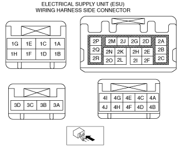
ELECTRICAL SUPPLY UNIT (ESU) INSPECTION
id094000003700
L.H.D
1. Disconnect the negative battery cable. (See NEGATIVE BATTERY CABLE DISCONNECTION/CONNECTION.)
2. Remove the following parts:
3. Connect the Electrical supply unit (ESU) connector.
4. Connect the negative battery cable. (See NEGATIVE BATTERY CABLE DISCONNECTION/CONNECTION.)
5. Verify that the voltages of each of the terminals are as indicated in the terminal voltage table (reference). (See Terminal Voltage Table (Reference).)
R.H.D
1. Disconnect the negative battery cable. (See NEGATIVE BATTERY CABLE DISCONNECTION/CONNECTION.)
2. Remove the following parts:
3. Connect the Electrical supply unit (ESU) connector.
4. Connect the negative battery cable. (See NEGATIVE BATTERY CABLE DISCONNECTION/CONNECTION.)
5. Verify that the voltages of each of the terminals are as indicated in the terminal voltage table (reference). (See Terminal Voltage Table (Reference).)
amxzzw00003938
|
Terminal Voltage Table (Reference)
|
Terminal |
Signal |
Connected to |
Measurement condition |
Voltage (V) |
Inspection item(s) |
|
|---|---|---|---|---|---|---|
|
1A
|
Ground
|
Body ground
|
Under any condition
|
1.0 or less
|
Body ground
|
|
|
1B
|
Door unlock control
|
• Door latch and lock actuator (LH)
• Fuel-filler lid lock actuator
|
Driver's door lock switch or fuel-filler lid lock actuator is unlocked
|
1.0 or less → Approx. 10 → 1.0 or less
|
• Door latch and lock actuator (LH)
• Fuel-filler lid lock actuator
|
|
|
Conditions other than above
|
1.0 or less
|
|||||
|
1C
|
Door lock control
|
• Door latch and lock actuator (LH), (RH)
• Fuel-filler lid lock actuator
|
Driver's door lock switch or fuel-filler lid lock actuator is locked
|
1.0 or less → Approx. 10 → 1.0 or less
|
• Door latch and lock actuator (LH), (RH)
• Fuel-filler lid lock actuator
|
|
|
Conditions other than above
|
1.0 or less
|
|||||
|
1D
|
Taillight, license plate light, rear side marker light control
|
• License plate light (LH), (RH)
• Taillight (LH)
• Rear side marker light (LH)
|
Ignition is switched ON (engine off or on)
|
Light switch is in TNS (Parking Lights) position
|
B+
|
• License plate light (LH), (RH)
• Taillight (LH)
• Rear side marker light (LH)
|
|
Light switch is in OFF position
|
1.0 or less
|
|||||
|
1E
|
2-step unlocking system control
|
Door latch and lock actuator (LH), (RH)
|
Press remote transmitter unlock button two times (2-step unlocking system operation condition)
|
1.0 or less → Approx. 10 → 1.0 or less
|
Door latch and lock actuator (LH), (RH)
|
|
|
Conditions other than above
|
1.0 or less
|
|||||
|
1F
|
—
|
—
|
—
|
—
|
—
|
|
|
1G
|
E latch motor control
|
Trunk lid latch and release actuator
|
Trunk is open
|
1.0 or less → Approx. 10 → 1.0 or less
|
Trunk lid latch and release actuator
|
|
|
Trunk is close
|
1.0 or less
|
|||||
|
1H
|
Ignition power supply
|
METER1 10 A fuse
|
Ignition is switched ON (engine off or on)
|
B+
|
METER1 10 A fuse
|
|
|
The ignition is switched off (LOCK)
|
1.0 or less
|
|||||
|
2A
|
Taillight, rear side marker light control
|
• Taillight (RH)
• Rear side marker light (RH)
|
Ignition is switched ON (engine off or on)
|
Light switch is in TNS (Parking Lights) position
|
B+
|
• Taillight (RH)
• Rear side marker light (RH)
|
|
Light switch is in OFF position
|
1.0 or less
|
|||||
|
2B
|
Power supply
|
TAIL 20 A fuse
|
Under any condition
|
B+
|
TAIL 20 A fuse
|
|
|
2C*1
|
Rear fog light relay control
|
Rear fog light
|
Ignition is switched ON (engine off or on)
|
Rear fog light switch is on
|
1.0 or less
|
Rear fog light
|
|
Rear fog light switch is off
|
B+
|
|||||
|
2D
|
Interior illumination power supply
|
• Steering switch
• Commander switch*2
• Audio unit*3
• CD player*4
• DVD/CD player*5
• Hazard warning switch
• Shift panel (indicator)
• Drive selection switch*6
• Cruise control switch
|
Ignition is switched ON (engine off or on)
|
Light switch is in ON position
|
B+
|
• Steering switch
• Commander switch*2
• Audio unit*3
• CD player*4
• DVD/CD player*5
• Hazard warning switch
• Shift panel (indicator)
• Drive selection switch*6
• Cruise control switch
|
|
Light switch is in OFF position
|
Voltage changes according to the tester specification, therefore determination is not possible.
|
|||||
|
2E
|
—
|
—
|
—
|
—
|
—
|
—
|
|
2F
|
Trunk compartment light power supply
|
Trunk compartment light
|
Ignition is switched ON (engine off or on) and trunk compartment light switched on
|
Trunk is opened
|
1.0 or less
|
Trunk compartment light
|
|
Trunk is closed
|
B+
|
|||||
|
2G
|
Ground
|
Body ground
|
Under any condition
|
1.0 or less
|
Body ground
|
|
|
2H
|
Serial communication
|
SAS control module
|
Terminal used for communication therefore determination based on terminal voltage is not possible.
|
|||
|
2I
|
LIN communication
|
Body control module (BCM)
|
Terminal used for communication therefore determination based on terminal voltage is not possible.
|
|||
|
2J
|
—
|
—
|
—
|
—
|
—
|
|
|
2K
|
—
|
—
|
—
|
—
|
—
|
|
|
2L
|
Map light power supply
|
Map light
|
Ignition is switched ON (engine off or on)
|
Interior light switch is in DOOR position and door is open
|
1.0 or less
|
Map light
|
|
Interior light switch is in DOOR position and door is closed
|
B+
|
|||||
|
2M
|
—
|
—
|
—
|
—
|
—
|
—
|
|
2N
|
—
|
—
|
—
|
—
|
—
|
|
|
2O
|
—
|
—
|
—
|
—
|
—
|
|
|
2P
|
Power supply
|
• INTERIOR 15 A fuse
• ROOM 25 A fuse
|
Under any condition
|
B+
|
• INTERIOR 15 A fuse
• ROOM 25 A fuse
|
|
|
2Q
|
Back-up light control
|
• Back-up light (LH), (RH)
• Auto-dimming mirror
|
Ignition is switched ON (engine off or on)
|
Selector lever is in R position
|
B+
|
• Back-up light (LH), (RH)
• Auto-dimming mirror
|
|
Conditions other than above
|
1.0 or less
|
|||||
|
2R
|
Power supply
|
• R.WIPER 15 A fuse
• CABIN+B 50 A fuse
|
Under any condition
|
B+
|
• R.WIPER 15 A fuse
• CABIN+B 50 A fuse
|
|
|
3A
|
Headlight high-beam control
|
Front combination light (RH)
|
Ignition is switched ON (engine off or on)
|
Light switch is in high-beam position
|
B+
|
Front combination light (RH)
|
|
Light switch is in position other than high-beam position
|
1.0 or less
|
|||||
|
3B
|
Power supply
|
H/L RH 20 A fuse
|
Under any condition
|
B+
|
H/L RH 20 A fuse
|
|
|
3C
|
Headlight low-beam control
|
Front combination light (RH)
|
Ignition is switched ON (engine off or on)
|
Light switch is in low-beam position
|
B+
|
Front combination light (RH)
|
|
Light switch in OFF position
|
1.0 or less
|
|||||
|
3D
|
Power supply
|
D.LOCK 25 A fuse
|
Under any condition
|
B+
|
D.LOCK 25 A fuse
|
|
|
4A
|
Headlight high-beam control
|
Front combination light (LH)
|
Ignition is switched ON (engine off or on)
|
Light switch is in high-beam position
|
B+
|
Front combination light (LH)
|
|
Light switch is in position other than high-beam position
|
1.0 or less
|
|||||
|
4B
|
Front washer motor control
|
Washer motor
|
Ignition is switched ON (engine off or on)
|
Front washer switch is on
|
B+
|
Windshield wiper motor
|
|
Front washer switch is off
|
1.0 or less
|
|||||
|
4C
|
Power supply
|
H/L LH 20 A fuse
|
Under any condition
|
B+
|
H/L LH 20 A fuse
|
|
|
4D
|
—
|
—
|
—
|
—
|
—
|
|
|
4E
|
Headlight low-beam control
|
Front combination light (LH)
|
Ignition is switched ON (engine off or on)
|
Light switch is in low-beam position
|
B+
|
Front combination light (LH)
|
|
Light switch in OFF position
|
1.0 or less
|
|||||
|
4F
|
—
|
—
|
—
|
—
|
—
|
|
|
4G
|
Parking light (RH) control
|
• Front combination light (RH)
• Front side marker light (RH)
|
Ignition is switched ON (engine off or on)
|
Light switch is in parking light position
|
B+
|
• Front combination light (RH)
• Front side marker light (RH)
|
|
Light switch is in position other than parking light position
|
1.0 or less
|
|||||
|
4H
|
—
|
—
|
—
|
—
|
—
|
|
|
4I
|
Parking light (LH) control
|
• Front combination light (LH)
• Front side marker light (LH)
|
Ignition is switched ON (engine off or on)
|
Light switch is in parking light position
|
B+
|
• Front combination light (LH)
• Front side marker light (LH)
|
|
Light switch is in position other than parking light position
|
1.0 or less
|
|||||
|
4J
|
Running light control
|
Front combination light (LH), (RH)
|
Ignition is switched ON (engine off or on)
|
Running light illuminates
|
B+
|
Front combination light (LH), (RH)
|
|
Running light turns off
|
1.0 or less
|
|||||