 |
amxuuw00002831
BODY CONTROL MODULE (BCM) REMOVAL/INSTALLATION
id094000003800
L.H.D.
AT
1. If the BCM is replaced and the auto configuration is not performed, perform the configuration using the M-MDS. (See BODY CONTROL MODULE (BCM) CONFIGURATION (USING READ/WRITE FUNCTION).)
2. Disconnect the negative battery cable. (See NEGATIVE BATTERY CABLE DISCONNECTION/CONNECTION.)
3. Remove the scuff plate (driver's side). (See SCUFF PLATE REMOVAL/INSTALLATION.)
4. Remove the front side trim (driver's side). (See FRONT SIDE TRIM REMOVAL/INSTALLATION.)
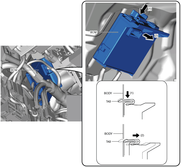
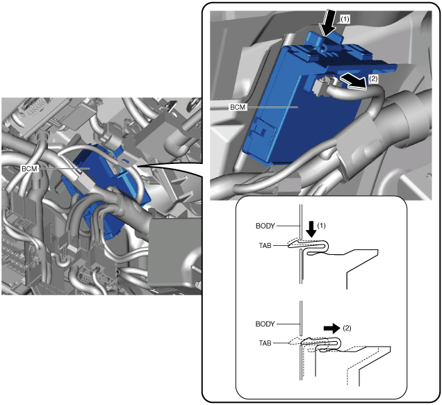
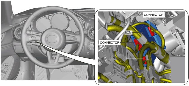
5. Remove the BCM connectors shown in the figure.
amxuuw00002831
|
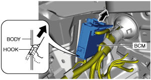
6. While pressing the BCM tab in the direction of arrow (1) shown in the figure, pull it in the direction of arrow (2) to detach the tab from the body.
amxuuw00002832
|
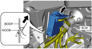
7. Pull the BCM in the direction of the arrow shown in the figure and detach the hook from the body.
amxzzw00002866
|
8. Remove the BCM.
9. Install in the reverse order of removal.
10. If the BCM is replaced and the auto configuration is performed, perform the auto configuration using the following procedure.
MT
1. If the BCM is replaced and the auto configuration is not performed, perform the configuration using the M-MDS. (See BODY CONTROL MODULE (BCM) CONFIGURATION (USING READ/WRITE FUNCTION).)
2. Disconnect the negative battery cable. (See NEGATIVE BATTERY CABLE DISCONNECTION/CONNECTION.)
3. Remove the scuff plate (driver's side). (See SCUFF PLATE REMOVAL/INSTALLATION.)
4. Remove the front side trim (driver's side). (See FRONT SIDE TRIM REMOVAL/INSTALLATION.)
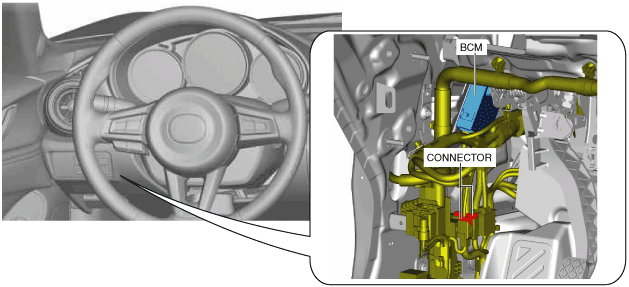
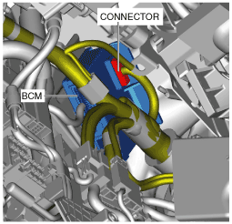
5. Disconnect the connector.
amxuuw00002833
|
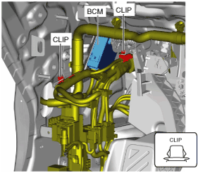
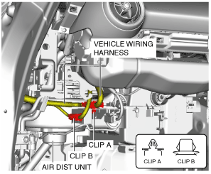
6. Remove the vehicle wiring harness clip.
amxuuw00002834
|
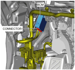
7. Remove the BCM connectors shown in the figure.
amxuuw00002835
|
8. While pressing the BCM tab in the direction of arrow (1) shown in the figure, pull it in the direction of arrow (2) to detach the tab from the body.
amxuuw00002836
|
9. Pull the BCM in the direction of the arrow shown in the figure and detach the hook from the body.
amxuuw00003715
|
10. Remove the BCM connector shown in the figure.
amxuuw00002837
|
11. Remove the BCM.
12. Install in the reverse order of removal.
13. If the BCM is replaced and the auto configuration is performed, perform the auto configuration using the following procedure.
R.H.D.
1. If the BCM is replaced and the auto configuration is not performed, perform the configuration using the M-MDS.(See BODY CONTROL MODULE (BCM) CONFIGURATION (USING READ/WRITE FUNCTION).)
2. Disconnect the negative battery cable.(See NEGATIVE BATTERY CABLE DISCONNECTION/CONNECTION.)
3. Remove the following parts:
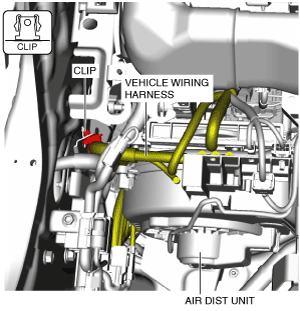
4. Remove the vehicle wiring harness clip.
amxzzw00002820
|
5. Remove the vehicle wiring harness clip.
amxzzw00002821
|
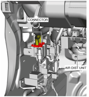
6. Disconnect the connectors.
amxzzw00002822
|
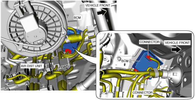
7. Disconnect the BCM connectors in the positions shown in the figure from under the air dist unit.
amxzzw00002823
|
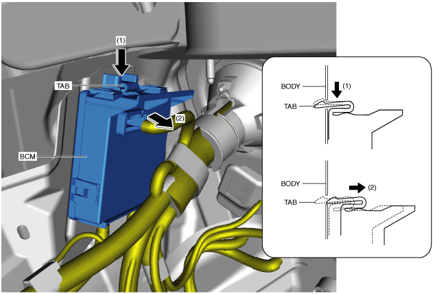
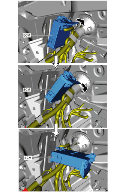
8. While pressing the BCM tab in the direction of arrow (1) shown in the figure, pull it in the direction of arrow (2) to detach the tab from the body.
amxzzw00002824
|
9. Pull the BCM in the direction of the arrow shown in the figure and detach the hook from the body.
amxzzw00002825
|
10. Rotate the BCM in the direction of the arrow shown in the figures and remove it.
amxzzw00002826
|
11. Install in the reverse order of removal.
12. If the BCM is replaced and the auto configuration is performed, perform the auto configuration using the following procedure.