 |
beleue00000039
VALVE CLEARANCE ADJUSTMENT [L8, LF]
id0110a9803300
1. Remove the battery and battery tray. (See BATTERY REMOVAL/INSTALLATION [L8, LF].)
2. Remove the plug hole plate. (See PLUG HOLE PLATE REMOVAL/INSTALLATION [L8, LF].)
3. Remove the air cleaner. (See INTAKE-AIR SYSTEM REMOVAL/INSTALLATION [L8, LF].)
4. Disconnect the ventilation hose. (See QUICK RELEASE CONNECTOR (EMISSION SYSTEM) REMOVAL/INSTALLATION [L8, LF].)
5. Remove the front suspension tower bar (joint). (See FRONT SUSPENSION TOWER BAR REMOVAL/INSTALLATION.)
6. Remove the CMP sensor. (See CAMSHAFT POSITION (CMP) SENSOR REMOVAL/INSTALLATION [L8, LF].)
7. Disconnect the oil control valve (OCV) connector. (With variable valve timing mechanism.)
8. Disconnect the P/S pressure switch connector.
9. Remove the ignition coils. (See IGNITION COIL REMOVAL/INSTALLATION [L8, LF].)
10. Remove the cylinder head cover. (See TIMING CHAIN REMOVAL/INSTALLATION [L8, LF].)
11. Remove the drive belt. (See DRIVE BELT REPLACEMENT [L8, LF].)
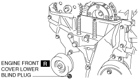
12. Remove the engine front cover lower blind plug.
beleue00000039
|
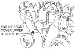
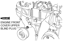
13. Remove the engine front cover upper blind plug.
amxzzw00002167
|
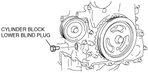
14. Remove the cylinder block lower blind plug.
15. Remove the under cover. (See TRANSVERSE MEMBER REMOVAL/INSTALLATION.)
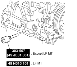
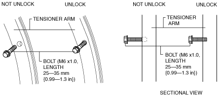
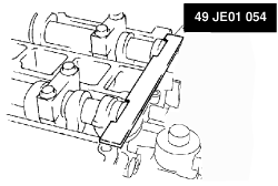
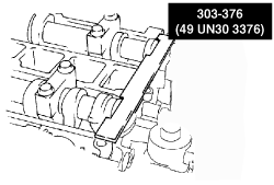
16. Install the SST as shown.
amxzzw00002168
|
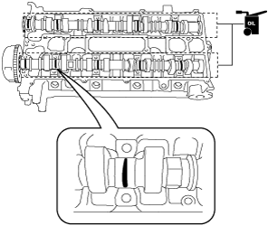
17. Turn the crankshaft clockwise until the crankshaft is in the No.1 cylinder TDC position.
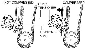
18. Loosen the timing chain using the following procedure.
beleue00000041
|
am8rrw00002539
|
am8rrw00002601
|
am8rrw00002541
|
beleue00000042
|
aprjjw00003610
|
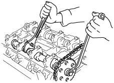
19. Hold the exhaust camshaft using a suitable wrench on the cast hexagon as shown.
amxzzw00001453
|
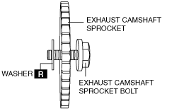
20. Remove the exhaust camshaft sprocket bolt, exhaust camshaft sprocket, and washer as a single unit.
beleue00000044
|
21. Remove the OCV. (With variable valve timing mechanism.) (See OIL CONTROL VALVE (OCV) REMOVAL/INSTALLATION [L8, LF].)
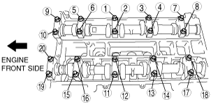
22. Loosen the camshaft cap bolts in several passes in the order shown.
e5u110zw5851
|
23. Remove the camshafts.
24. Remove the tappet.
25. Select proper adjustment tappet.
26. Apply the gear oil (SAE No. 90 or equivalent) to each journal of the cylinder head as shown in the figure.
amxzzw00001454
|
27. Install the camshaft with No.1 cylinder aligned with the TDC position.
28. Apply the gear oil (SAE No. 90 or equivalent) to each journal of the camshaft as shown in the figure.
amxzzw00001455
|
29. Tighten the camshaft cap bolt with the following two steps.
e5u110zw5852
|
30. Install the OCV. (With variable valve timing mechanism.) (See OIL CONTROL VALVE (OCV) REMOVAL/INSTALLATION [L8, LF].)
31. Install the exhaust camshaft sprocket bolt, exhaust camshaft sprocket, and a new washer as a single unit.
am3zzw00004783
|
32. Install the SST to the camshaft as shown.
Europe
amxzzw00001456
|
Except Europe
amxzzw00001457
|
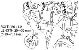
33. Remove the M6 X 1.0 bolt (length 25mm—35mm {0.99in—1.37in}) from the engine front cover to apply tension to the timing chain.
34. Turn the crankshaft clockwise until the crankshaft is in the No.1 cylinder TDC position.
35. Hold the exhaust camshaft using a suitable wrench on the cast hexagon as shown.
am8rrw00002546
|
36. Tighten the exhaust camshaft sprocket bolt.
37. Remove the SST from the camshaft.
38. Remove the SST from the block lower blind plug.
39. Rotate the crankshaft clockwise two turns until the TDC position.
40. Apply silicone sealant to the engine front cover upper blind plug.
41. Install the engine front cover upper blind plug.
amxzzw00002169
|
42. Install the cylinder block lower blind plug.
am8rrw00002588
|
43. Install the new engine front cover lower blind plug.
beleue00000039
|
44. Install the drive belt. (See DRIVE BELT REPLACEMENT [L8, LF].)
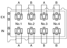
45. Measure the valve clearance.
amxzzw00001458
|
46. Install the cylinder head cover. (See TIMING CHAIN REMOVAL/INSTALLATION [L8, LF].)
47. Install the ignition coils. (See IGNITION COIL REMOVAL/INSTALLATION [L8, LF].)
48. Connect the OCV connector. (With variable valve timing mechanism.)
49. Install the CMP sensor. (See CAMSHAFT POSITION (CMP) SENSOR REMOVAL/INSTALLATION [L8, LF].)
50. Install the front suspension tower bar (joint). (See FRONT SUSPENSION TOWER BAR REMOVAL/INSTALLATION.)
51. Connect the ventilation hose. (See QUICK RELEASE CONNECTOR (EMISSION SYSTEM) REMOVAL/INSTALLATION [L8, LF].)
52. Install the air cleaner. (See INTAKE-AIR SYSTEM REMOVAL/INSTALLATION [L8, LF].)
53. Install the plug hole plate. (See PLUG HOLE PLATE REMOVAL/INSTALLATION [L8, LF].)
54. Install the battery and battery tray. (See BATTERY REMOVAL/INSTALLATION [L8, LF].)