VALVE CLEARANCE INSPECTION [L8, LF]
id0110a9803400
1. Remove the battery cover. (See BATTERY REMOVAL/INSTALLATION [L8, LF].)
2. Disconnect the negative battery cable. (See BATTERY REMOVAL/INSTALLATION [L8, LF].)
3. Remove the plug hole plate. (See PLUG HOLE PLATE REMOVAL/INSTALLATION [L8, LF].)
4. Disconnect the ventilation hose. (See QUICK RELEASE CONNECTOR (EMISSION SYSTEM) REMOVAL/INSTALLATION [L8, LF].)
5. Remove the front suspension tower bar (joint). (See FRONT SUSPENSION TOWER BAR REMOVAL/INSTALLATION.)
6. Remove the CMP sensor. (See CAMSHAFT POSITION (CMP) SENSOR REMOVAL/INSTALLATION [L8, LF].)
7. Disconnect the oil control valve (OCV) connector. (With variable valve timing mechanism.)
8. Disconnect the P/S pressure switch connector.
9. Remove the ignition coils. (See IGNITION COIL REMOVAL/INSTALLATION [L8, LF].)
10. Remove the cylinder head cover. (See TIMING CHAIN REMOVAL/INSTALLATION [L8, LF].)
11. Measure the valve clearance.
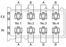
- (1) Turn the crankshaft clockwise so that the No.1 piston is at TDC of the compression stroke.
- (2) Measure the valve clearance at A in the figure.
-
-
• If the valve clearance is out of the specification, adjust it. (See
VALVE CLEARANCE ADJUSTMENT [L8, LF].)
-
Note
-
• Make sure to note down the measured values for choosing the suitable replacement tappets.
-
Valve clearance [Engine cold]
-
IN: 0.22—0.28 mm {0.0087—0.0110 in}
EX: 0.27—0.33 mm {0.0107—0.0129 in}
- (3) Turn the crankshaft 360° clockwise so that the No.4 piston is at TDC of the compression stroke.
- (4) Measure the valve clearance at B in the figure.
-
-
• If the valve clearance is out of the specification, adjust it. (See
VALVE CLEARANCE ADJUSTMENT [L8, LF].)
-
Note
-
• Make sure to note down the measured values for choosing the suitable replacement tappets.
-
Valve clearance [Engine cold]
-
IN: 0.22—0.28 mm {0.0087—0.0110 in}
EX: 0.27—0.33 mm {0.0107—0.0129 in}
12. Install the cylinder head cover. (See TIMING CHAIN REMOVAL/INSTALLATION [L8, LF].)
13. Install the ignition coils. (See IGNITION COIL REMOVAL/INSTALLATION [L8, LF].)
14. Connect the P/S pressure switch connector.
15. Connect the OCV connector. (With variable valve timing mechanism.)
16. Install the CMP sensor. (See CRANKSHAFT POSITION (CKP) SENSOR REMOVAL/INSTALLATION [L8, LF].)
17. Install the front suspension tower bar (joint). (See FRONT SUSPENSION TOWER BAR REMOVAL/INSTALLATION.)
18. Connect the ventilation hose. (See QUICK RELEASE CONNECTOR (EMISSION SYSTEM) REMOVAL/INSTALLATION [L8, LF].)
19. Install the plug hole plate. (See PLUG HOLE PLATE REMOVAL/INSTALLATION [L8, LF].)
20. Connect the negative battery cable. (See BATTERY REMOVAL/INSTALLATION [L8, LF].)
21. Install the battery cover.